Energy-saving and efficient licker-in cleaning device for textile machinery

A technology for textile machinery and cleaning devices, which is applied in the field of energy-saving and high-efficiency licker-in roller cleaning devices for textile machinery, which can solve the problems of time-consuming, laborious, and low cleaning efficiency, and achieve good results, high cleaning efficiency, and reduced use and waste.

Pending Publication Date: 2021-10-01
黄译炜
View PDF6 Cites 3 Cited by
  • Summary
  • Abstract
  • Description
  • Claims
  • Application Information

AI Technical Summary

Problems solved by technology

[0005] The object of the present invention is to provide an energy-saving and high-efficiency type licker-in roller cleaning device for textile machinery with high cleaning efficiency and good effect in view of the above-mentioned problems of low cleaning efficiency and time-consuming and labor-intensive problems.

Method used


Image

  • Energy-saving and efficient licker-in cleaning device for textile machinery
  • Energy-saving and efficient licker-in cleaning device for textile machinery
  • Energy-saving and efficient licker-in cleaning device for textile machinery

Examples


Embodiment 1

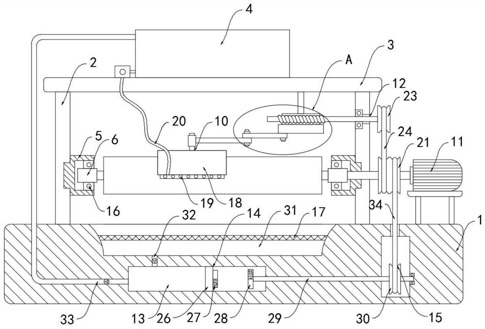
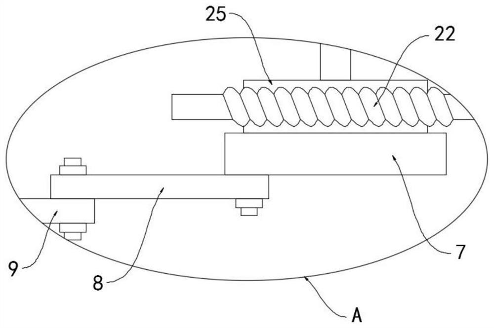
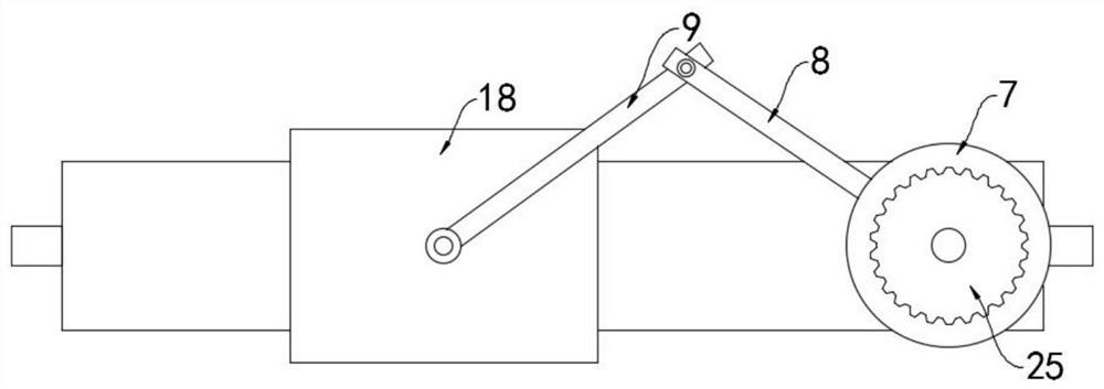
[0029] like Figure 1-5 As shown, an energy-saving and high-efficiency licker-in roller cleaning device for textile machinery includes a base 1 and two side plates 2 fixedly installed on the upper surface of the base 1, the upper ends of the side plates 2 are fixedly connected with a top plate 3, and the upper surface of the top plate 3 A water storage tank 4 is provided, and a rotating seat 5 is installed on the side walls of the two side plates 2 that are close to each other. The rotating seat 5 is rotatably connected with a rotating sleeve 6, and the rotating shafts at both ends of the licker-in roller can extend into the rotating sleeve 6. , when the rotating sleeve 6 rotates, the licker-in roller is driven by friction to rotate. It is worth mentioning that the rotating sleeve 6 is connected to the rotating seat 5 through the rotating bearing 16, and the outer ring of the rotating bearing 16 is fixedly connected to the rotating seat 5. Ring is fixedly connected with rotati...

Embodiment 2

[0038] like Image 6 As shown, the difference between this embodiment and Embodiment 1 lies in that: the arc-shaped brush plate 18 is made of elastic rubber material, and a plurality of magnet blocks 35 are equidistantly embedded in the arc-shaped brush plate 18 .

[0039] In this embodiment, the magnet block 35 can generate a magnetic attraction force to the iron licker-in roller, thereby impelling the arc-shaped brush plate 18 to deform and fit and wrap on the licker-in roller surface, so as to ensure the brushing effect of the arc-shaped brush plate 18 on the licker-in roller, and , The arc-shaped brush plate 18 can change its bending radian according to licker-in rollers of different diameters and sizes, and has a wide range of applications.


PUM


Abstract

The invention belongs to the technical field of textile equipment, and particularly relates to an energy-saving and efficient licker-in cleaning device for textile machinery, which comprises a base and two side plates fixedly mounted on the upper surface of the base; a top plate is fixedly connected to the upper ends of the side plates; a water storage tank is arranged on the upper surface of the top plate; rotating seats are installed on the side walls, close to each other, of the two side plates; rotating sleeves are rotatably connected into the rotating seats; a horizontal cam is arranged below the top plate; a transmission rod is rotatably connected to the position, deviating from the circle center, of the lower surface of the cam; a connecting rod is rotatably connected to the end, away from the cam, of the transmission rod; a brushing mechanism is arranged at the end, away from the transmission rod, of the connecting rod; and a driving motor is mounted on the upper surface of the base. An arc-shaped brush plate can be used for brushing a licker-in in the circumferential direction and the axial direction in all directions, the cleaning efficiency is high, the cleaning effect is good, water flows back into the water storage tank through a backflow mechanism, cleaning water can be recycled, and waste of water resources is reduced.

Description

technical field [0001] The invention belongs to the technical field of textile equipment, and in particular relates to an energy-saving and high-efficiency type licker-in roller cleaning device for textile machinery. Background technique [0002] With the rapid development of the textile industry, the demand for textile machinery is increasing. Textile machinery is the production means and material basis of the textile industry. Its technical level, quality and manufacturing cost are directly related to the development of the textile industry. Textile machinery consists of Composed of multiple parts, the textile licker-in roller is an important part of textile machinery, mainly used for carding textiles and improving the quality of textiles. [0003] After the existing licker-in roller is used for a long time, it needs to be cleaned to avoid a large amount of textile fibers or dust stains entangled in the licker-in roller, which will reduce its carding effect. There are two ...

Claims


Application Information

Patent Timeline
Patent Type & Authority Applications(China)
IPC IPC(8): B08B1/00B08B1/02B08B3/02B08B3/14B08B13/00
CPCB08B1/002B08B1/02B08B3/022B08B3/14B08B13/00
Inventor 黄译炜
Owner 黄译炜
Why Eureka
Try Eureka