Submersible vehicle laying and recovering device with variable structure and laying and recovering method thereof

A technology for retractable devices and submersibles, which is applied in lifting devices, transportation and packaging, ships, etc., can solve the problems of lack of motion adjustment mechanism, potential safety hazards for large personnel, and inability to meet the needs of submersible retraction, etc., to achieve flexible structure, The effect of high safety and stability

Pending Publication Date: 2021-10-01
TIANJIN UNIV
View PDF10 Cites 1 Cited by
  • Summary
  • Abstract
  • Description
  • Claims
  • Application Information

AI Technical Summary

Problems solved by technology

Existing patents such as "A Structure-Adjustable Submersible Suspension Point Externally Mounted Recovery Device and Method" (Patent No.: CN106744258A) adopt a cage-type recovery device, which has a fixed structure and lacks a motion adjustment mechanism. If the submersible The irregular movement of the submersible due to the influence of wind and waves is easy to collide with the recovery device, which will cause damage to the sensors on the surface of the multi-joint submersible and damage the submersible.
For example, the patent of "a submersible retractable device" (patent number: CN110001895B) is composed of three groups of grasping arms, which can satisfy the deployment and recovery of submersibles in still water, but in complex sea conditions, the operation is difficult and it is not easy to guarantee the submersible. Safe and efficient recovery deployment
For example, "A Manufacturing Method for Retractable Device of Underwater Glider and Unmanned Submersible Vehicle" (Patent No.: CN109050839A) uses an inclined track to retract and deploy the submersible, which can reduce the impact of wind and waves during the deployment of the submersible. However, due to the lack of flexibility in the orbital angle and structure, it is difficult to recover the submersible
[0004] Most submersibles have a rigid structure, and they can move forward and backward through the propeller at the tail, and cannot move laterally
Therefore, when recovering, it is difficult to drive into the mechanism quickly and accurately
If manual assisted recycling is used, there will be a greater potential safety hazard for personnel
Especially when the sea is rough and the waves are strong, the recycling process is difficult and time-consuming
It can be seen that most of the existing deployment devices cannot meet the needs of submersible retraction and deployment under complex sea conditions, and cannot avoid collisions and violent swings during the retraction and deployment process, and it is difficult to ensure the efficiency and safety of retraction and deployment. Therefore, more Advanced and reliable retractable device and control method

Method used


Image

  • Submersible vehicle laying and recovering device with variable structure and laying and recovering method thereof
  • Submersible vehicle laying and recovering device with variable structure and laying and recovering method thereof
  • Submersible vehicle laying and recovering device with variable structure and laying and recovering method thereof

Examples


Embodiment 1

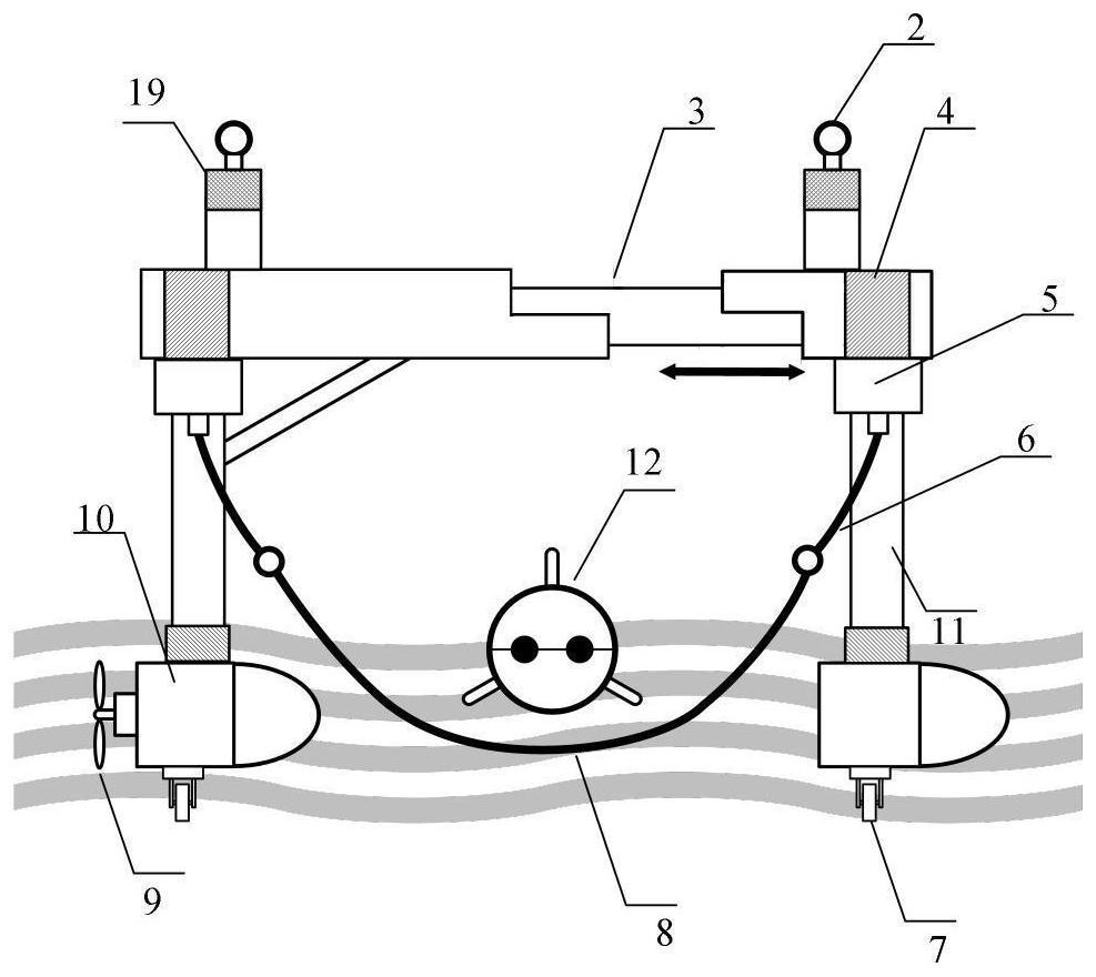
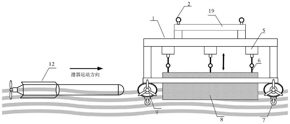
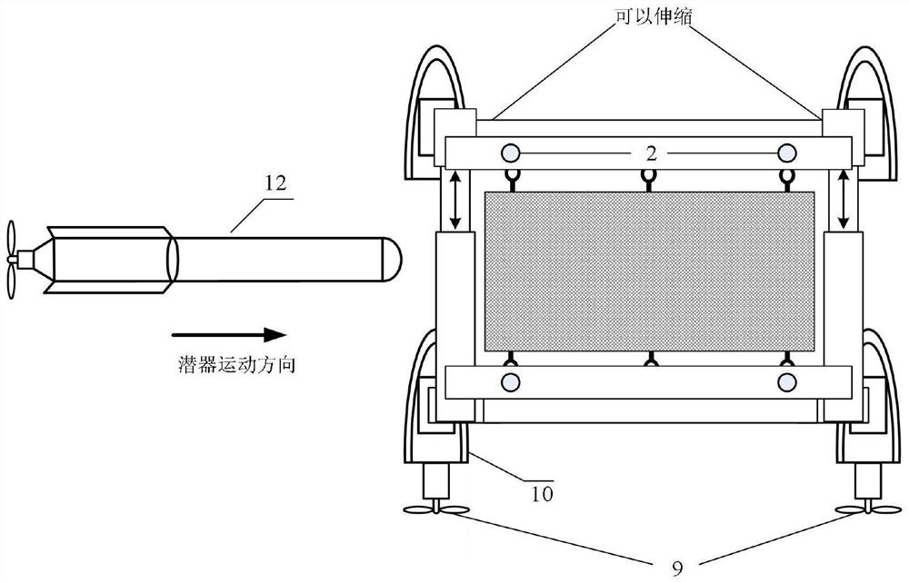
[0039] Such as figure 1 A retractable device with a variable structure is shown, which is used for recovery and deployment of various submersibles in complex sea conditions. 12 is composed of two parts: an electrical control system and a retractable mechanism system. Among them, the electrical control system includes the main control module, electrical drive module, communication module and power supply management module; the retractable mechanism system includes device moving equipment, telescopic equipment and submersible receiving equipment. The mobile equipment is composed of a buoyancy base 1 and a propeller 9; the telescopic equipment is composed of a portal bracket 1, a telescopic mechanism 3, a servo motor and a fixed bracket 6; And load-bearing net 8 constitutes. The upper part of the door-shaped bracket 1 is connected by a telescopic mechanism 3, through which the width of the door-shaped bracket 1 can be changed, winches 5 are installed on the pillars on both sides...

Embodiment 2

[0060] Such as Figure 6 A retractable device with a variable structure is shown, the telescopic equipment and receiving equipment in the electrical control system and the retractable mechanism system of embodiment 2 are exactly the same as those in embodiment 1, and the position and quantity of buoyancy base 1 are also the same as those in embodiment 2. Example 1 remains the same, but propeller 9 is not installed.

[0061] Such as Figure 7 The schematic diagram of the A-frame crane of the mother ship is shown, the A-type 15 frame is equipped with a crane, and the connection between the crane and the A-frame 15 is provided with a horizontal motor 16. The crane can be displaced on the horizontal track 17 by the horizontal motor 16, and its position is adjusted to cooperate with the submersible.

[0062] Such as Figure 8 and Figure 9 The schematic diagram of the hoisting and retracting mechanism shown by the crane adopts the A-frame structure in the invention patent "A Sh...


PUM


Abstract

The invention relates to a submersible vehicle laying and recovering device with a variable structure. The device comprises an electrical control system and a laying and recovering mechanism system; the electrical control system comprises a main control module, three electrical driving modules connected with the main control module, a communication module and a power supply management module; and the laying and recovering mechanism system comprises a device moving mechanism, a support mechanism and a submersible vehicle bearing mechanism. The support mechanism comprises two sets of telescopic door-shaped supports which are arranged side by side, each set of telescopic door-shaped support comprises fixing supports located at the two sides and a telescopic mechanism erected on the fixing supports at the two sides, and the telescopic mechanisms can change the width of the door-shaped supports under driving of a first electric driving module. The submersible vehicle bearing mechanism comprises an electric capstan, a twisted rope and a bearing net, a plurality of lifting ropes are connected to the two sides of the bearing net respectively, and the lifting ropes on the two sides are connected to the two top cross beams through lifting rings and the electric capstan respectively. The invention further provides a laying method and a recovery method of the submersible vehicle.

Description

technical field [0001] The invention relates to the field of deployment and recovery of underwater vehicles, in particular to a recovery and deployment device suitable for torpedo-shaped submersibles. Background technique [0002] The submersible can operate in the deep sea for a long time and long distance, and its main tasks mainly include seabed exploration, seabed monitoring, and underwater tasks. Retrieval and deployment are important links in the operation process of submersibles, which involve the availability and applicability of underwater unmanned submersibles. Usually, the deployment and recovery of the submersible is directly hoisted by the crane or A-frame of the mother ship. Since submersibles usually operate in the open sea, the sea conditions in the open sea are relatively complicated and the wind and waves are relatively large. The submersible swings violently with the waves on the water surface, making the recovery process difficult and inefficient. The s...

Claims


Application Information

Patent Timeline
Patent Type & Authority Applications(China)
IPC IPC(8): B63C11/52B63B23/40B63B23/48
CPCB63C11/52B63B23/40B63B23/48
Inventor 刘迎澍程果孟庆浩
Owner TIANJIN UNIV
Why Eureka
Try Eureka