Mobile emergency lighting control method and device

A technology of emergency lighting and control devices, which is applied in the field of emergency lighting, can solve the problems of cumbersome installation and debugging of mobile lighting equipment, and achieve the effects of flexible lighting direction, convenient and fast installation and debugging, and preventing dragging

Active Publication Date: 2021-10-01
OPTRAFFIC CO LTD
View PDF6 Cites 1 Cited by
  • Summary
  • Abstract
  • Description
  • Claims
  • Application Information

AI Technical Summary

Problems solved by technology

[0005]In view of this, the first purpose of the present invention is to provide a mobile emergency lighting control method, which mainly solves the cumbersome installation and debugging process of existing mobile lighting equipment The problem

Method used


Image

  • Mobile emergency lighting control method and device
  • Mobile emergency lighting control method and device
  • Mobile emergency lighting control method and device

Examples


Embodiment 1

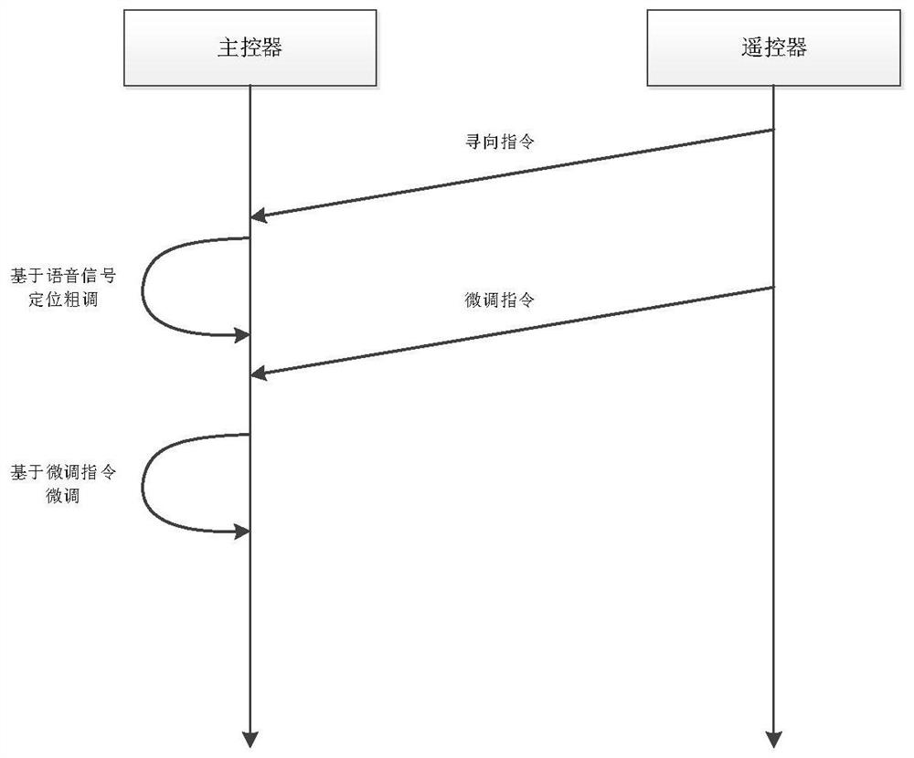
[0040] Such as figure 1 As shown, a mobile emergency lighting control method includes the following steps:

[0041] S1: The mobile lighting vehicle arrives at the first predetermined position, and sends a direction-finding start command to the main controller on the mobile lighting vehicle through the remote control;

[0042] S2: The main controller starts the direction finding process, and the voice positioning device in the main controller collects the voice command sent by the user from the second predetermined position;

[0043] S3: the voice positioning device determines the direction and distance of the second predetermined position relative to the first predetermined position by analyzing the voice command collected in step S2, and roughly adjusts the height adjustment device and the direction adjustment device on the mobile lighting vehicle;

[0044] S4: sending a fine-tuning instruction to the main controller on the mobile lighting vehicle through the remote controll...

Embodiment 2

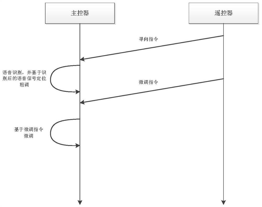
[0048] Such as figure 2 As shown, this embodiment provides a mobile emergency lighting control method. The difference between this method and Embodiment 1 is that during voice control, the system performs voice recognition in advance, and only when the collected voice command is a system preset command, the Execute the corresponding operation; otherwise, the system waits for an action or gives a voice prompt.

[0049] Since the voice positioning device usually uses the sound source localization method based on the microphone array to determine the position where the user sends out the voice command, the main controller can randomly select the voice command collected by one of the microphones to compare with the preset command when performing voice recognition. Compared. For example, the system uses "light, light" as a preset voice command. When the user shouts "light, light", the main controller randomly selects a voice signal collected by a microphone for judgment, and thro...


PUM


Abstract

The invention discloses a mobile emergency lighting control method and device. The method achieves the positioning according to a voice instruction sent by a user, thereby preliminarily determining the relative relation between the position where the user sends a voice and the position where a mobile lighting vehicle is located, and automatically achieving the preliminary adjustment of the height and direction of lighting equipment. If the light irradiation direction slightly shifts, a fine adjustment instruction is sent out through the remote controller, so that rapid debugging of the mobile emergency lighting equipment is realized. The device is compact in structure, convenient to move and capable of rapidly arriving at a place needing emergency lighting, a height adjusting device can achieve synchronous stretching and retracting of multiple sections of masts through cooperation of a hydraulic cylinder and a bearing rope, the structure is stable, the bearing capacity is high, and rod dragging can be effectively prevented; and by designing the structure of a lamp holder, the horizontal angle and the pitching angle of the lighting assembly can be adjusted, the lighting direction is more flexible, and the lighting assembly can better adapt to different application scenes.

Description

technical field [0001] The invention relates to the technical field of emergency lighting, in particular to a mobile emergency lighting control method and device. Background technique [0002] When working in emergency, disaster relief, construction and other occasions at night, large-area, high-brightness temporary light source equipment is required to provide lighting. At present, the commonly used solution is to temporarily build lighthouses and install lamps. However, this method not only takes a long time to build, but also has poor adaptability to the site. If there is no power facility near the site, cables must be pulled over long distances, and it is difficult to adjust the lighting height and angle. [0003] In view of this, some mobile light towers have also appeared on the market, such as a mobile light tower disclosed in the Chinese invention patent application with application number 201210312308.0, which includes a car body, a lifting component and a lighting ...

Claims


Application Information

Patent Timeline
IPC IPC(8): F21L4/08F21V21/06F21V21/15F21V21/22F21V23/00
CPCF21L4/08F21V21/06F21V21/15F21V21/22F21V23/003Y02B20/40
Inventor 徐新宇
Owner OPTRAFFIC CO LTD
Why Eureka
Try Eureka