Supercharge Your Innovation With Domain-Expert AI Agents!

Die Bonder and Die Bonding Method

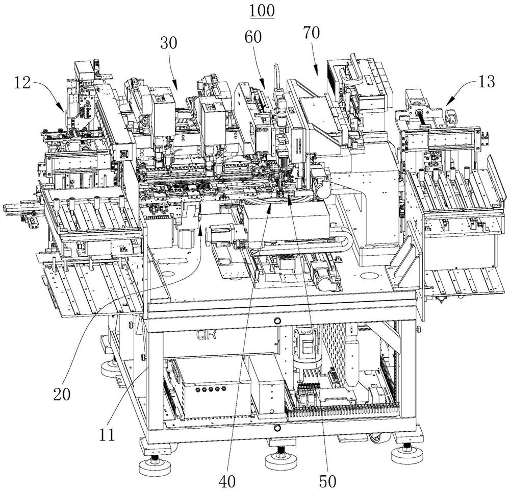
A die-bonding machine and die-bonding technology, applied in semiconductor/solid-state device manufacturing, electrical components, circuits, etc., can solve problems such as low die-bonding precision, and achieve the effect of ensuring the quality and precision of die-bonding

Active Publication Date: 2022-04-19
SHENZHEN XINYICHANG TECH CO LTD
View PDF9 Cites 0 Cited by
  • Summary
  • Abstract
  • Description
  • Claims
  • Application Information

AI Technical Summary

Problems solved by technology

[0003] The purpose of the embodiments of the present application is to provide a die bonding machine and a die bonding method to solve the problem of low die bonding precision existing in the prior art

Method used


Image

  • Die Bonder and Die Bonding Method
  • Die Bonder and Die Bonding Method
  • Die Bonder and Die Bonding Method

Examples


Embodiment Construction

[0057] In order to make the technical problems, technical solutions and beneficial effects to be solved by the present application clearer, the present application will be further described in detail below in conjunction with the accompanying drawings and embodiments. It should be understood that the specific embodiments described here are only used to explain the present application, and are not intended to limit the present application.

[0058] It should be noted that when an element is referred to as being “fixed” or “disposed on” another element, it may be directly on the other element or be indirectly on the other element. When an element is referred to as being "connected to" another element, it can be directly connected to the other element or indirectly connected to the other element.

[0059] In addition, the terms "first" and "second" are used for descriptive purposes only, and cannot be interpreted as indicating or implying relative importance or implicitly specify...


PUM


Abstract

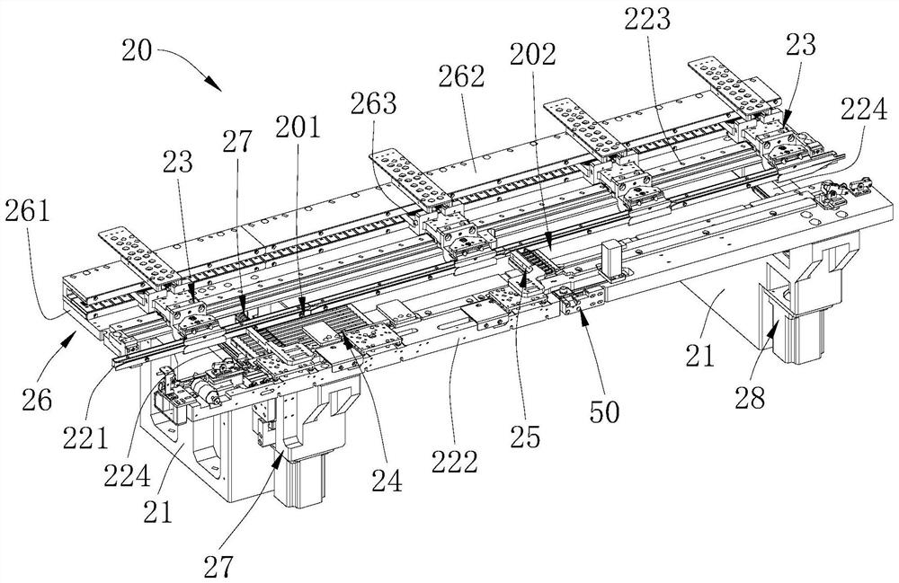
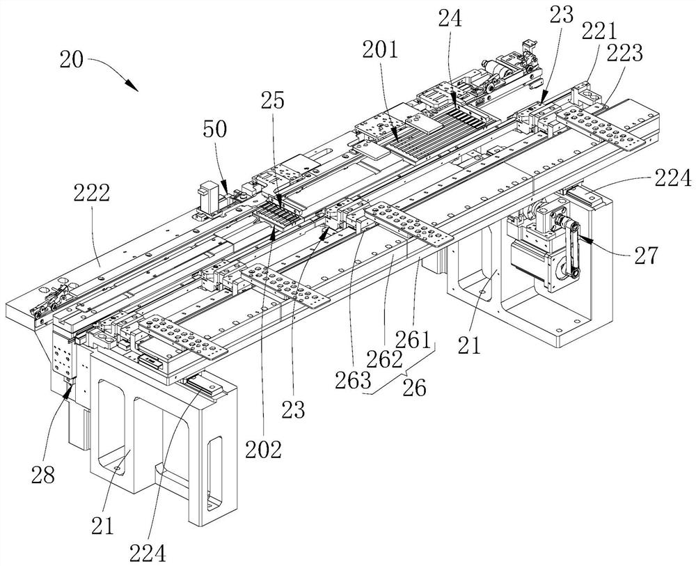
The application provides a crystal bonding machine and a crystal bonding method; the crystal bonding machine includes: a feeding mechanism; a receiving mechanism; a track mechanism; a film expanding crystal supply mechanism; a glue dispensing mechanism; The welding head mechanism is used to transfer the wafer supplied by the expansion film supply mechanism to the correction mechanism for angle correction, and then transfers the corrected wafer to the bracket of the solid crystal position; and the lens mechanism is used to provide visual positioning . This application corrects the angle of the wafer through the calibration mechanism, and provides visual positioning through the lens mechanism, so that the expanding film feeding mechanism can position and supply the wafer, so that the calibration mechanism can be accurately calibrated, and it is convenient for the welding head mechanism to accurately absorb the wafer and install it on the bracket. To ensure the precision and quality of die bonding.

Description

technical field [0001] The present application belongs to the technical field of semiconductor crystal bonding, and more specifically relates to a crystal bonding machine and a crystal bonding method. Background technique [0002] Die bonding generally uses a glue dispenser to dispense glue on the position where the chip is installed on the bracket. Then it is moved to the crystal bonding position, and the crystal bonding head sucks the wafer from the film expansion and crystal supply mechanism, and then places it on the support to realize the crystal bonding. Because the expansion film supply mechanism generally adjusts the position of the wafer on the blue film by moving the platform horizontally, and then rotates the blue film to correct the angle of the wafer. Then it is absorbed and installed on the bracket by the solid crystal head. However, the expanded film supply mechanism is to perform rotation correction on the wafer on the entire blue film, especially after the...

Claims


Application Information

Patent Timeline
Patent Type & Authority Patents(China)
IPC IPC(8): H01L21/67H01L21/68H01L21/50
CPCH01L21/67121H01L21/681H01L21/50
Inventor 胡新平梁志宏
Owner SHENZHEN XINYICHANG TECH CO LTD
Features
  • R&D
  • Intellectual Property
  • Life Sciences
  • Materials
  • Tech Scout
  • Unparalleled Data Quality
  • Higher Quality Content
  • 60% Fewer Hallucinations
Learn More