

Control method of Vienna rectifier under power grid imbalance
A technology of power grid imbalance and control method, which is applied in the direction of electrical components, high-efficiency power electronic conversion, output power conversion device, etc., can solve the problems of output voltage secondary ripple, rectifier input current distortion, etc., and achieve simple control method, beneficial effect
- Summary
- Abstract
- Description
- Claims
- Application Information
AI Technical Summary
Problems solved by technology
Method used
Image

Examples
Embodiment 1
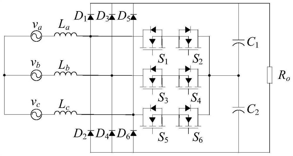
[0047] figure 1 Shown is the applied Vienna rectifier topology of the present invention, among the figure v a , v b , v c is the three-phase input voltage, L a , L b , L c is the input inductance, D 1 ~D 6 is the diode, S 1 ~S 6 is the switching tube, C 1 、C 2 is the output capacitance, R 0 for the load.
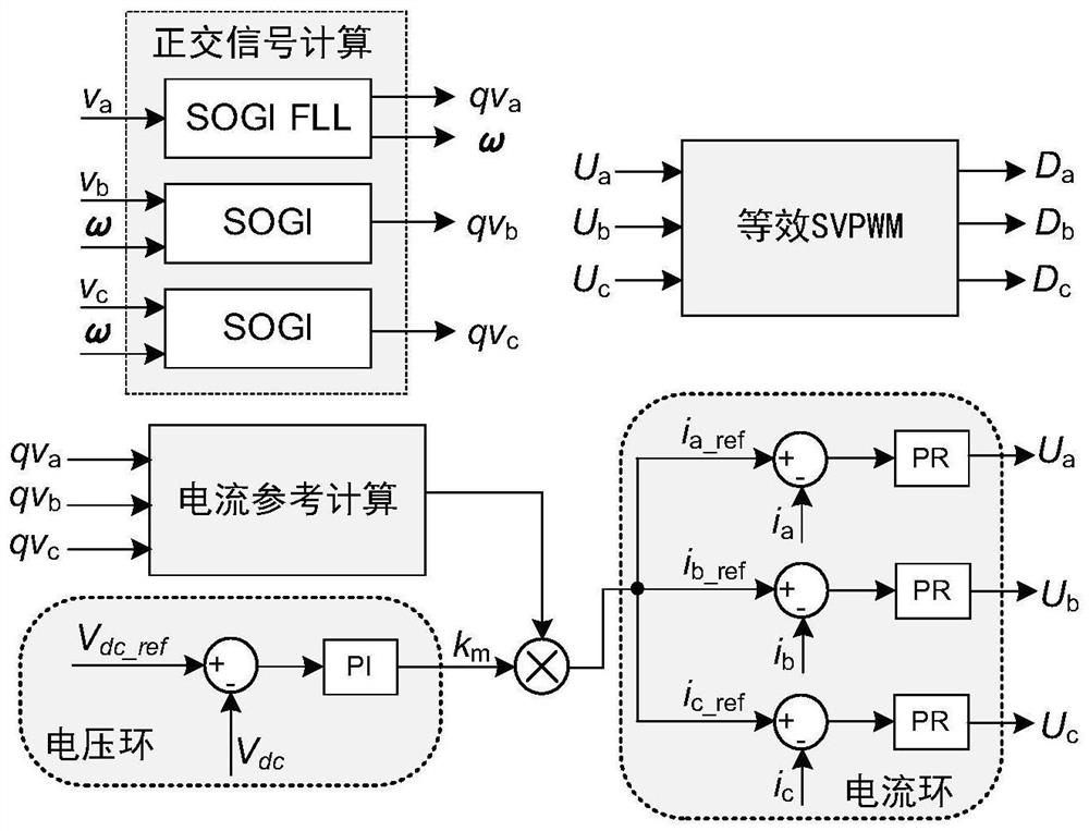
[0048] figure 2 Shown is the principle diagram of the Vienna rectifier control method under the unbalanced power grid of the present invention. In the present embodiment, the switching frequency of the Vienna rectifier is 200kHz, and the sampling frequency of the DSP digital controller is 100kHz. The control steps during operation include the following parts:
[0049] 1) The DSP digital controller samples the three-phase input voltage signal v of the Vienna rectifier in the grid a , v b , v c , three-phase input current signal i a i b i c and the output voltage signal V dc .
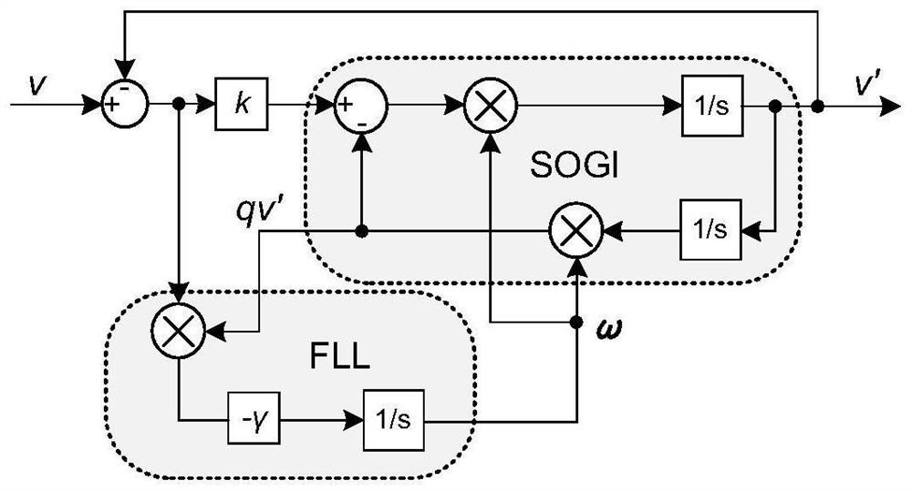
[0050] 2) The three-phase input voltage signal v a , v b , v c pass imag...
example 1
[0068] Utilize the Vienna rectifier control method under unbalanced power grid in this embodiment, build a simulation model on the PLECS simulation software, and simulate the Vienna rectifier in aviation applications, the steps are as follows:
[0069] 1) Set the effective value of input voltage A-phase 103V, B-phase 115V, C-phase 126V, there is 10% unbalance in three-phase voltage, input voltage frequency is 400Hz, output voltage is 360V, output power is 4.5kW, switching frequency is 200kHz, sampling frequency 100kHz, input inductance 150μH, output capacitance 440μF.
[0070] 2) Adopt conventional voltage and current double-loop PI control, by Figure 7 It can be seen that the input current of the rectifier is distorted, the total harmonic distortion (THD) of the input current reaches 4.89%, and the output voltage has a secondary ripple of about 6V.
[0071] 3) Using the proposed control method under unbalanced power grid, the Figure 8 It can be seen that the harmonic cont...
experiment example 1
[0076] Using the Vienna rectifier control method under unbalanced power grid in this embodiment, the experimental verification is carried out through the 4.5kW aviation Vienna rectifier prototype platform, and the steps are as follows:
[0077] 1) Set the effective value of the input voltage of the three-phase input source: A-phase 103V, B-phase 115V, C-phase 126V, there is a 10% unbalance in the three-phase voltage, the input voltage frequency is 400Hz, the output voltage is 360V, the output power is 4.5kW, and the switching frequency is 200kHz , the sampling frequency is 100kHz, the input inductance is 150μH, and the output capacitance is 440μF.
[0078] 2) Adopt conventional voltage and current double-loop PI control, by Figure 11 It can be seen that the input current of the rectifier is distorted, the total harmonic distortion (THD) of the input current reaches 8.54%, and the output voltage has a secondary ripple of about 3.5V.
[0079] 3) Using the proposed control meth...
PUM
 Abstract
Description
Claims
Application Information