Cleaning instrument for treating inner cervical tract in obstetrics and gynecology department

A technology of obstetrics and gynecology and cervix, which is applied in the direction of obstetrics and gynecology equipment, can solve the problems of slow effect and long medication cycle, and achieve the effect of convenient operation and reducing cervical discomfort

Active Publication Date: 2021-10-08
陕西善美生物药业有限公司
View PDF7 Cites 1 Cited by
  • Summary
  • Abstract
  • Description
  • Claims
  • Application Information

AI Technical Summary

Problems solved by technology

[0004] The purpose of the present invention is: in order to solve the problem of slow effect and long

Method used


Image

  • Cleaning instrument for treating inner cervical tract in obstetrics and gynecology department
  • Cleaning instrument for treating inner cervical tract in obstetrics and gynecology department
  • Cleaning instrument for treating inner cervical tract in obstetrics and gynecology department

Examples


Embodiment 1

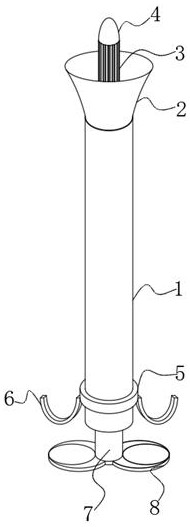
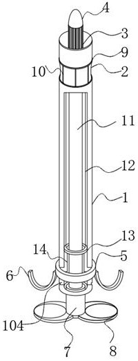
[0031] See Figure 1-9 , An obstetrics and gynecology is used to treat the cleaning instruments of cervical inner roads, including;

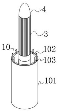
[0032] Used to insert the silicone tube 1 through the expansion of the expander, including the tubular body 101, the top of the tube 101 is provided with an annular inner tank 102, located at the top of the annular inner tank 102, an open outer ring 103 is provided, and the left and right sides of the surface thereof. The vertical groove 104 is provided, and the bayonet is opened on the side of the inner wall of the vertical groove 104;

[0033] The kernel cleaning rod 3 is fixed to the top of the silicone tube 1 inserted into the top of the silicone tube 1, and the top of the joint is disposed at the bottom of the silicone tube 1, and the link 5 is provided. The side is fixedly coupled to the finger sleeve 6, and the silica tube 1 is inserted and the coupling is provided with a movable ring 13, and the movable ring 13 is fixed by the connecting rod ...

Embodiment 2

[0038] Based on the above embodiment on which the compression rod 38 comprises two fixed base 381, two opposite side of the holder 381 is provided with slots 383 and plunger 382, ​​the plunger 382 into the slot 383, slot 383 defines one side of a limiting groove 384, the sleeve 385 is provided with the pressing plate and the slide plate 386 in the slot 383, the plunger 382 and the side of the pressing plate 385 is fixedly connected to the slide plate 386 by the compression spring 387 and the elastic inner wall slot 383 connection, the sliding plate 386 has one side hinged rocker lever 388, one end of the rocker lever 39 hinged lever 388 is hinged, the lever 388 defines Alice chute 389, a guide rod 3810 is inserted, the guide rod is fixedly connected to the chute 389 3810 on one side of the inner wall 384 of the stopper groove;

[0039] The compression rod 38 when subjected to compression, is provided on the two holder 381 into the slot 382 within the plunger 383, the plunger 382 p...


PUM


Abstract

The invention discloses a cleaning instrument for treating an inner cervical tract in the obstetrics and gynecology department, and belongs to the technical field of obstetrics and gynecology departments. The cleaning instrument for treating the inner cervical tract in the obstetrics and gynecology department comprises an inserting silicone tube used for penetrating through a vaginal speculum; the inserting silicone tube comprises a tube body; an annular embedded groove is formed in the top of the tube body; an open outer ring is arranged at the top of the annular embedded groove; after a clamping piece is ejected out of a through groove, a cleaning layer is unfolded into an arc shape from an M shape; furthermore, the outer surface of the cleaning layer protrudes and can stably make contact with the inner wall of the cervix uteri; in this way, an inner channel cleaning rod can be conveniently inserted into the cervix uteri; the cleaning layers which are arranged at equal intervals can be perfectly in contact with the inner wall of the cervix uteri in the unfolding process; the purpose of real-time adjustment can be achieved according to the radial distance of the cervix uteri in the rotating process; a falling channel can be reserved in the scraping process; stickies can be rapidly discharged; and, according to the internal squamous characteristics, attachments in squamous gaps can be quickly removed.

Description

Technical field [0001] The present invention belongs to the technical field of maternity, and in particular to an obstetrics and gynecology for the treatment of cervical inner road cleaning instruments. Background technique [0002] The cervix is ​​in the lower part of the uterus, approximately from 2.5 ~ 3cm, and the upper end is connected to the uterus. The lower end is deep into the vagina, and the cervical epithelium is composed of the squamous epithelium of the cervical vagin and the cervical epithelial epithelium. The two handover is outside the cervix. The mouth, called the original scales exchange department or the branch of the scale. However, this handover area is not constant and will be affected by estrogen. If the estrogen level is high, the columnar epithelium can be expanded outward, accounting for some of the palace neck. The cervical columnar epithelial is known as "cervical erosion", mainly due to the pillar epidemic very good, and the capillaries in the followi...

Claims


Application Information

Patent Timeline
IPC IPC(8): A61B17/42
CPCA61B17/42A61B2017/4225
Inventor 颜达立
Owner 陕西善美生物药业有限公司
Why Eureka
Try Eureka