Jet dispensing equipment for chip packaging

A technology of chip packaging and injection point, which is applied in the direction of injection device, device for coating liquid on the surface, coating, etc., can solve the problems of circuit board scrapping, deviation, uneven extrusion, etc., and achieve quality assurance and simple and ingenious structure , Extrude the glue smoothly and evenly

Pending Publication Date: 2021-10-08
浙江巨创半导体科技有限公司
View PDF1 Cites 6 Cited by
  • Summary
  • Abstract
  • Description
  • Claims
  • Application Information

AI Technical Summary

Problems solved by technology

[0005] The purpose of the present invention is to address the shortcomings of the prior art and provide a chip packaging injection dispensing device. By setting the glue pushing assembly on the glue outlet pipe, the sliding block of the glue pushing assembly can cut off the glue supply section and the The glue outlet section, so that a certain amount of glue is left in the glue outlet section when spraying glue, and then the quantitative glue in the glue outlet section is squeezed and sprayed around the chip by using the glue pushing piston in the second cavity. When a single type of product is packaged, the amount of glue extruded each time is quantitative. The quantitative glue can be determined by setting the size of the inner space of the glue section, which ensures that the amount of glue used for the packaging of a single type of product is constant and controllable, avoiding the need for Some glue spraying equipment has a large deviation in the amount of glue extruded each time when extruding glue, and the extrusion is uneven, and the glue spraying cannot be stopped in time when the translational driving force fails, which may easily cause the entire circuit board to be scrapped.

Method used


Image

  • Jet dispensing equipment for chip packaging
  • Jet dispensing equipment for chip packaging
  • Jet dispensing equipment for chip packaging

Examples


Embodiment 1

[0035] Embodiments of the present invention will be described in detail below, and examples of the embodiments are illustrated in the drawings, in which the same or similar reference numerals represent the same or similar elements or elements having the same or similar functions. The following is exemplary, and is intended to be used to illustrate the invention without understanding the limitation of the invention.

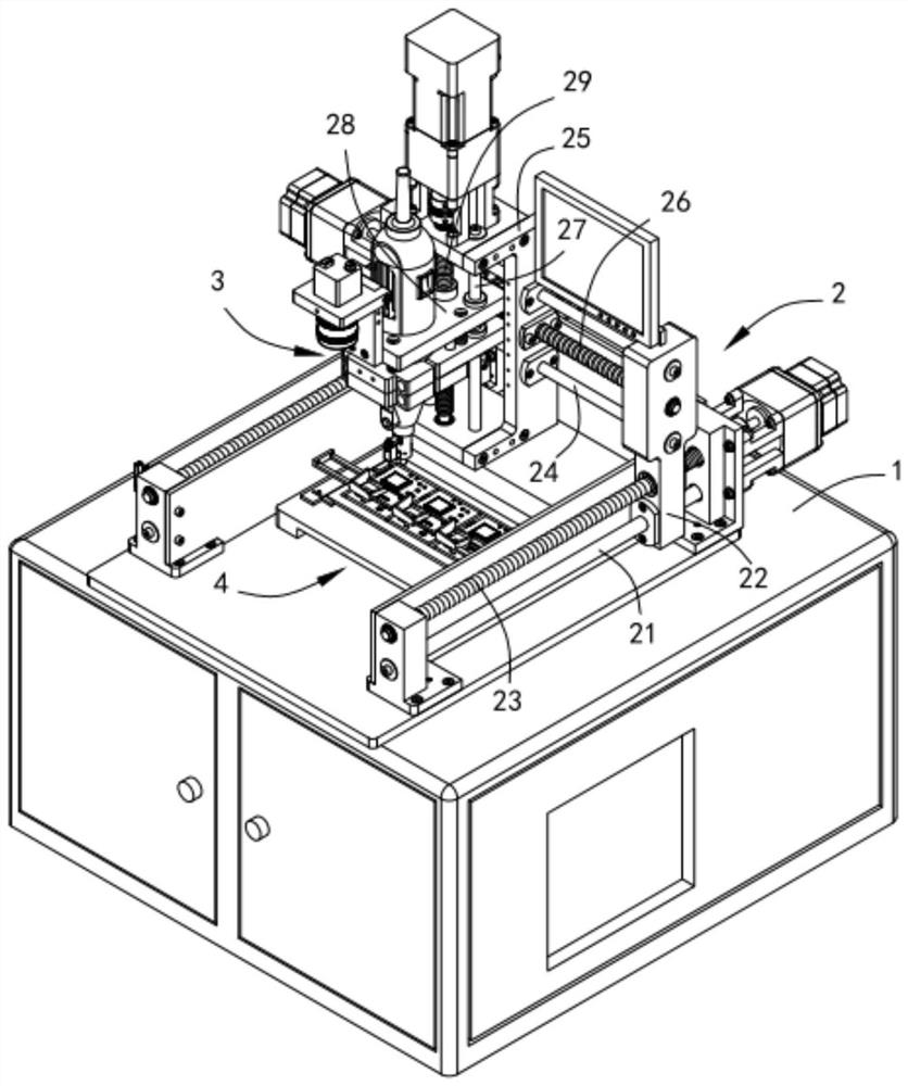
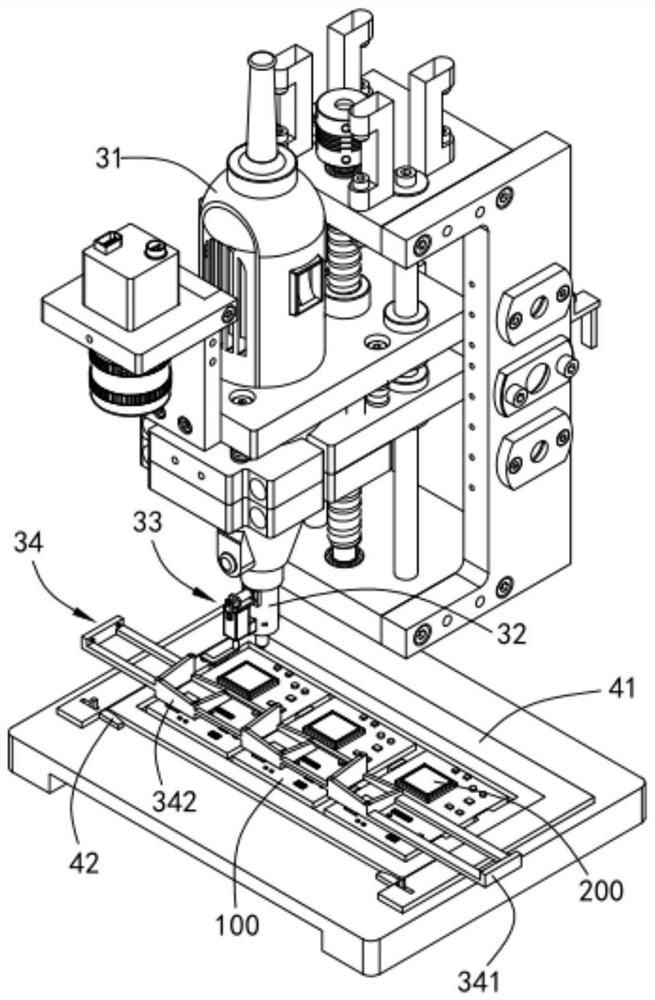
[0036] like Figure 1 to 9 As shown, a chip package is encapsulated, including a seat 1, a drive mechanism 2 disposed on the seat 1, moving a dispensing mechanism 3 that moves under the drive mechanism 2 and is provided below the dispensing mechanism 3 and fixed The positioning clamp 4 on the seat 1, the dot rubber mechanism 3 includes a tub 31 and an elongate tube 32 disposed at the bottom of the tub 31, which includes a glue segment 10 and a glue section 20, said A pilot assembly 33 is provided between the glue segment 10 and the outset section 20, and corresponding ...

Embodiment 2

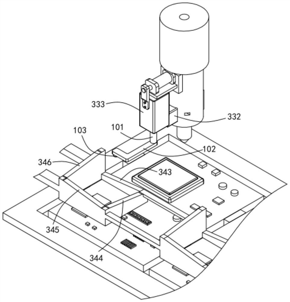
[0049] like Figure 8 with Figure 9 Shown, wherein the same as in Example a, or a respective corresponding parts are designated by reference numerals embodiment, for simplicity, the following description only a point of difference with the embodiment embodiment; different from the first embodiment according to the second embodiment of the in that: further, the end surface of the pushing rubber piston 331 is provided with a blade 6, the side of the second cavity 336 further defines a clean mouth 7, defines an upper wall of the hose 32 are communication port 8, while the second cavity 336 slides to the communication port 8 at the location of the communication port 8 communicating with the cleaning port 7.

[0050] In this embodiment, the inner wall can be of a rubber section 20 is pushed in a plastic squeegee upper portion of the piston 331 is provided such that the blade 6 is reset each time after the completion of spray, avoiding the inner wall of the plastic section 20 Accumulatio...


PUM


Abstract

The invention relates to jet dispensing equipment for chip packaging. The equipment comprises a machine base, a driving mechanism, a dispensing mechanism driven by the driving mechanism and a positioning clamp arranged below the dispensing mechanism, wherein the dispensing mechanism comprises a glue barrel and a glue outlet pipe arranged at the bottom of the glue barrel, the glue outlet pipe comprises a glue supply section and a glue outlet section, a glue pushing assembly is arranged between the glue supply section and the glue outlet section, a guiding assembly cooperating with the glue pushing assembly is arranged above the positioning clamp accordingly, the glue pushing assembly is used for cutting off communication between the glue supply section and the glue outlet section before glue dispensing operation, and a glue pushing piston arranged in the glue pushing assembly is pushed downwards to extrude glue along an inner wall of the glue outlet section by means of pneumatic pressure under the action of the guiding assembly during the glue dispensing operation. The equipment solves the problems that when glue spraying equipment extrudes the glue, the amount of the glue extruded each time has large deviation, extrusion is uneven, when a translation driving force fault occurs, glue spraying cannot be stopped in time, so that a whole circuit board is easily scrapped. And when a translation driving force fault occurs, glue spraying cannot be stopped in time, so that the whole circuit board is easily scrapped.

Description

Technical field [0001] The present invention relates to the technical field of semiconductor production equipment, and in particular, a chip package injection dot rubber device. Background technique [0002] During the production of semiconductor board, it is necessary to perform spray packages around it after completing the chip. [0003] The application number is a Chinese practical new type patent for CN201821743123.4, which discloses an automatic spraying device for LED chip packaging, including transport tracks, and parallel-axis drive mechanisms, two y-axis drive mechanisms above the transport track. The setting direction is perpendicular to the direction of operation of the transport rail, and the Y-axis drive mechanism is slidably connected to the X-axis drive mechanism, and the X-axis drive mechanism is provided with a split mechanism, and the lower portion of the spray mechanism is provided with a split needle, located below the X-axis drive mechanism. A limit lock mech...

Claims


Application Information

Patent Timeline
Patent Type & Authority Applications(China)
IPC IPC(8): B05C5/02B05C11/10B05B15/50B05B15/55
CPCB05C5/0212B05C11/1002B05B15/50B05B15/55B05C11/1039
Inventor 彭连波
Owner 浙江巨创半导体科技有限公司
Why Eureka
Try Eureka