Dust-falling spraying device and dust-falling spraying system for mine
A spray device and dust suppression technology, applied in safety devices, dust prevention, mining equipment, etc., can solve the problems of complex structure, inconvenient control, easy to cause dangerous accidents, etc., and achieve the effect of simple use and control
- Summary
- Abstract
- Description
- Claims
- Application Information
AI Technical Summary
Problems solved by technology
Method used
Image
Examples
Embodiment 1
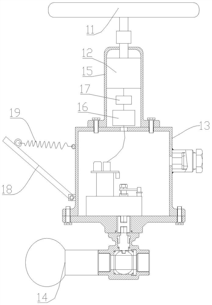
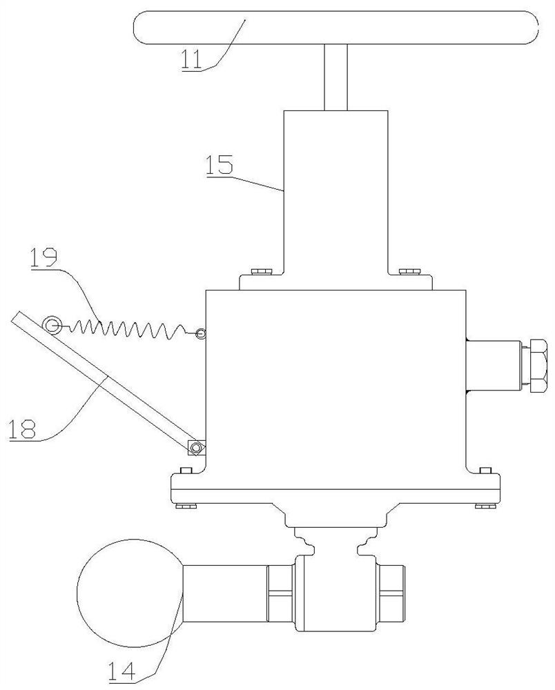
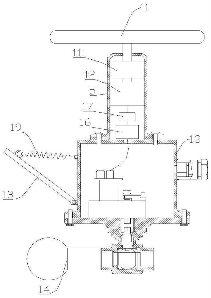
[0033] Such as Figure 1-3 As shown, the present embodiment provides a dust suppression spray device 1, including a rotating member 11, a power generating device 12, an electric control valve 13 and a spray assembly 14, the rotating member 11 is connected to the power generating device 12, and the generating device 12 is connected to the above-mentioned The electric control valve 13 is electrically connected, and the output end of the electric control valve 13 is connected with the spray assembly 14 .
[0034] In this embodiment, when in use, the input end of the electric control valve 13 is connected to the infusion pipeline, and the rotating member 11 rotates to drive the power generation device 12 to generate electricity, so that the power generation device 12 generates electric energy, so that the electric control valve 13 obtains an electric signal, and the electric signal makes The electric control valve 13 is opened, so that the liquid in the infusion pipeline enters th...
Embodiment 2
[0036] Such as Figure 1-3 As shown, this embodiment is based on the above-mentioned embodiment 1, and the above-mentioned rotating member 11 is a driving wheel, and the rotating shaft of the above-mentioned driving wheel is connected to the above-mentioned power generation device 12 through transmission.
[0037]In this embodiment, the rotating member 11 is a driving wheel, and the driving wheel has a simple structure. Directly controlling the rotation of the driving wheel can make the generator generate electricity, thereby controlling the opening of the electric control valve 13 to reduce dust.
[0038] Using the driving wheel as the rotating member 11, on the premise of realizing its rotating function, on the one hand, the cost is low, and the operation is simple; on the other hand, the structure is simple, and the overall weight is light, easy to carry, and easy to install.
[0039] In some implementations of this embodiment, an acceleration gear set 111 may be provided b...
Embodiment 3
[0043] Such as Figure 1-3 As shown, this embodiment further includes an energy storage device 16 on the basis of some of the above-mentioned embodiments, and the energy storage device 16 is electrically connected between the above-mentioned power generation device 12 and the above-mentioned electric control valve 13 .
[0044] In this embodiment, the energy storage device 16 can store the electric energy generated by the power generation device 12 in the energy storage device 16, and then the energy storage device 16 will provide an electric signal to the electric control valve 13, so that the electric control valve 13 can be opened, so that During the dust removal process of the device, the excess electric energy generated by driving the generator through the driving wheel will be stored in the energy storage device 16. When the driving device stops rotating and the power generation device 12 stops generating electricity, the energy storage device 16 can still continue to gen...
PUM
 Abstract
Description
Claims
Application Information
 - R&D
- Intellectual Property
- Life Sciences
- Materials
- Tech Scout
- Unparalleled Data Quality
- Higher Quality Content
- 60% Fewer Hallucinations
Browse by: Latest US Patents, China's latest patents, Technical Efficacy Thesaurus, Application Domain, Technology Topic, Popular Technical Reports.
© 2025 PatSnap. All rights reserved.Legal|Privacy policy|Modern Slavery Act Transparency Statement|Sitemap|About US| Contact US: help@patsnap.com


