Liquid hydrogen storage type hydrogen refueling station mixed filling system

A technology of a filling system and a hydrogen filling station, which is applied in the field of a mixed filling system for a liquid hydrogen storage type hydrogen filling station, can solve the problems of large energy consumption, low hydrogen storage capacity, and single filling form of the hydrogen filling station, and achieves The effect of reducing energy consumption and improving filling capacity

Active Publication Date: 2021-10-08
SOUTHEAST UNIV
View PDF7 Cites 5 Cited by
  • Summary
  • Abstract
  • Description
  • Claims
  • Application Information

AI Technical Summary

Problems solved by technology

Domestic hydrogen refueling stations are mainly high-pressure hydrogen storage hydrogen refueling stations, and most of them can only refill hydrogen fuel cell vehicles using 35MPa vehicle-mounted hydrogen storage bottles. The filling technology for 70MPa vehicle-mounted hydrogen storage bottles is still in the research and development stage. Less use in hydrogen stations
The defects of the current hydrogen refueling stations using high-pressure technology for hydrogen storage are: 1. The hydrogen storage capacity is low, and the daily hydrogen refueling capacity is 200kg / day, which can only basically meet the refueling requirements of vehicles during small-scale demonstration operations, and cannot meet the requirements of With the development of the hydrogen fuel cell vehicle industry, there is an increasing demand for filling volume; 2. Only 35MPa high-pressure hydrogen can be filled, and the filling form is single, which cannot take into account the 35MPa and 70MPa passenger car hydrogen storage cylinders currently on the market 3. It is necessary to cool the hydrogen at the filling outlet, and the energy consumption of the hydrogen refueling station is relatively large

Method used


Image

  • Liquid hydrogen storage type hydrogen refueling station mixed filling system
  • Liquid hydrogen storage type hydrogen refueling station mixed filling system

Examples


Embodiment Construction

[0015] In order to deepen the understanding of the present invention, the present invention will be further described below in conjunction with the accompanying drawings. This embodiment is only used to explain the present invention, and does not constitute a limitation to the protection scope of the present invention.

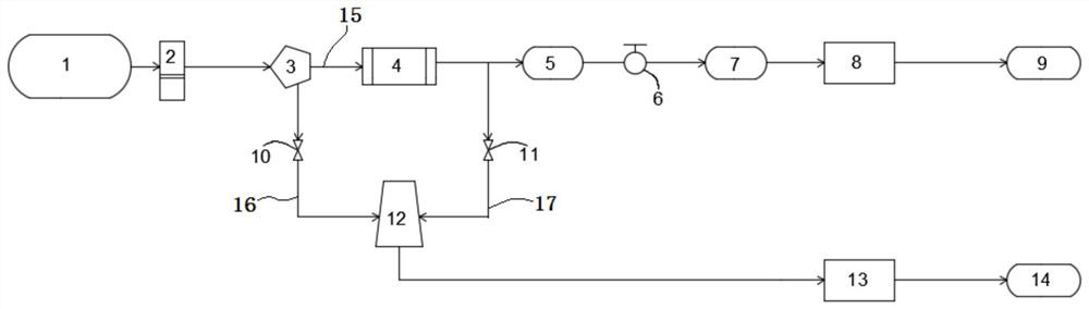
[0016] figure 1 It shows a liquid hydrogen storage type hydrogen filling station hybrid filling system, including a 35MPa hydrogen filling unit and a 70MPa hydrogen filling unit connected to the station liquid hydrogen storage tank 1, and the 35MPa hydrogen filling unit includes sequentially connected The first liquid hydrogen delivery pipe 15, the high-pressure vaporizer 4, the 90MPa buffer bottle group 5, the 45MPa buffer bottle group 7, and the first hydrogenation machine 8, the input end of the first liquid hydrogen delivery pipe 15 is connected to the station through the liquid hydrogen pump 2 The liquid hydrogen storage tank 1 is connected; the 70MPa hyd...


PUM


Abstract

The invention discloses a liquid hydrogen storage type hydrogen refueling station mixed filling system. The system comprises a 35 MPa hydrogen filling unit and a 70 MPa hydrogen filling unit which are connected with a liquid hydrogen storage tank, each of the two filling units comprises a liquid hydrogen pump communicating with the liquid hydrogen storage tank, a fluid separator for changing the flow direction and flow of hydrogen and a high-pressure vaporizer, the 35MPa hydrogen filling unit further comprises a 90MPa buffer bottle group, a 45MPa buffer bottle group and a first hydrogen filling machine, and the 70MPa hydrogen filling unit further comprises a second liquid hydrogen conveying pipe, a high-pressure hydrogen conveying pipe, a gas-liquid mixer and a second hydrogen adding machine. The system has the advantages that the hydrogen storage capacity is large, the energy consumption is low, and the filling requirements of different forms of hydrogen can be met.

Description

technical field [0001] The invention relates to the technical field of liquid hydrogen refueling stations, in particular to a liquid hydrogen storage type hydrogen refueling station mixing filling system. Background technique [0002] Hydrogen refueling stations are mainly divided into two types: high-pressure hydrogen storage and refueling stations and liquid hydrogen storage and refueling stations. At present, the technology of foreign liquid hydrogen storage and refueling stations is relatively mature. Bottles are filled. Domestic hydrogen refueling stations are mainly high-pressure hydrogen storage hydrogen refueling stations, and most of them can only refill hydrogen fuel cell vehicles using 35MPa vehicle-mounted hydrogen storage bottles. The filling technology for 70MPa vehicle-mounted hydrogen storage bottles is still in the research and development stage. It is less used in hydrogen stations. The defects of the current hydrogen refueling stations using high-pressur...

Claims


Application Information

Patent Timeline
Patent Type & Authority Applications(China)
IPC IPC(8): F17C5/04F17C13/00F17C13/04
CPCF17C5/04F17C13/00F17C13/04Y02P90/45Y02E60/32
Inventor 倪中华严岩李永平李仕豪
Owner SOUTHEAST UNIV
Why Eureka
Try Eureka