Heat dissipation device and light source assembly with same

A heat dissipation device and light source component technology, which is applied to the components of lighting devices, cooling/heating devices of lighting devices, electric light sources, etc., can solve the problems of increased stress on lamp balls, fried lamps, and affecting light transmission, etc., to delay qualitative changes , Improve the service life and prolong the life of the light source

Pending Publication Date: 2021-10-08
陈卫洪
View PDF10 Cites 0 Cited by
  • Summary
  • Abstract
  • Description
  • Claims
  • Application Information

AI Technical Summary

Problems solved by technology

For stage lamps or other high-power light sources, a lot of heat will be generated during work, especially the surface temperature of the lamp ball can often reach hundreds of degrees Celsius or even nearly a thousand degrees Celsius, so it is necessary to dissipate heat from the light source to avoid light source Not functioning properly or failing prematurely due to insufficient heat dissipation
[0003] Among them, the most common heat dissipation method is to use a fan to dissipate heat from the light source; however, in the prior art, when a fan is simply used to dissipate heat from the light source, there will be a problem of unbalanced heat dissipation. ) is often fixed, that is, the airflow of the fan can only blow to a certain area on the light source, and the light source is a three-dimensional sphere (ultra-high pressure mercury lamp) or tubular body (UV medium pressure tube), lamp ball or Some areas of the lamp tube are bound to be cold or hot
For example, during the working process of mercury lamps, metal halide lamps, and ultraviolet lamps, which are high-pressure gas discharge lamps, the tungsten inside the lamp bulb tends to accumulate in the colder position on the inner wall of the lamp bulb. Due to the opacity of tungsten, it will Rapid heat absorption, which in turn leads to excessive local temperature, which will cause the overheating reaction of the light source (bulb) glass / quartz, such as whitening, etc.; which will further lead to an increase in the stress of the lamp bulb, and eventually lead to the overheating of the lamp bulb due to excessive stress. Fatal failures such as cold cracking and fried lamps due to
Furthermore, besides being sensitive to supercooling, mercury lamps are also more sensitive to overheating. Because the glass or quartz in the mercury lamp has an upper limit of temperature, when the temperature exceeds a certain temperature, the glass or quartz will form devitrification phenomenon. , affect the light transmission, and will make the heat trapped inside the light source and cannot be radiated out through the light, which will further deteriorate the temperature of the lamp bulb and shorten the service life of the light source

Method used


Image

  • Heat dissipation device and light source assembly with same
  • Heat dissipation device and light source assembly with same
  • Heat dissipation device and light source assembly with same

Examples


Embodiment Construction

[0047] The technical solutions of the present invention will be described in further detail below in conjunction with the accompanying drawings and specific embodiments, so that those skilled in the art can better understand the present invention and implement it. In this embodiment, it should be understood that the terms "portrait", "horizontal", "upper", "lower", "front", "rear", "left", "right", "vertical", "horizontal" "," "top", "bottom", "inside", "outside" and other indicated orientations or positional relationships are based on the orientations or positional relationships shown in the drawings, and are only for the convenience of describing the present invention, rather than indicating or implying The device or element referred to must have a particular orientation, be constructed and operate in a particular orientation, and therefore should not be construed as limiting the invention.

[0048] It should be noted that when an element is referred to as being "connected" ...


PUM


Abstract

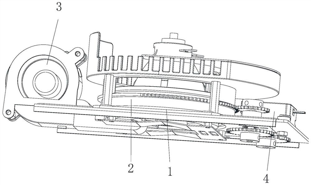
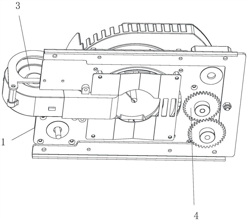
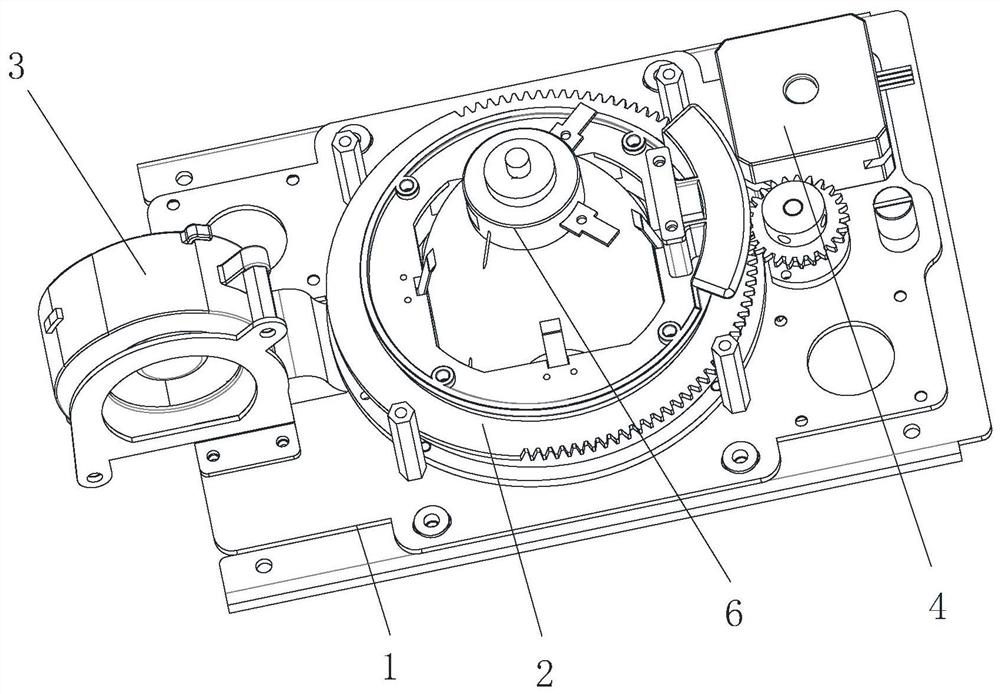
The invention relates to a heat dissipation device and a light source assembly with same, which comprises a base, a light source installation base, a heat dissipation mechanism, a driving mechanism and a light source, the light source installation base and the driving mechanism are both connected with the base, the driving mechanism is in transmission connection with the light source installation base, the driving mechanism is used for driving the light source mounting seat to rotate relative to the base, the heat dissipation mechanism is connected with the base and corresponds to the light source mounting seat, the light source is connected with the light source mounting seat, and the heat dissipation mechanism is used for dissipating heat of a light source mounted on the light source mounting seat; and the heat dissipation device and the light source assembly have the advantages of being reasonable in structure and capable of improving heat dissipation balance of the light source.

Description

technical field [0001] The invention belongs to the technical field of lighting equipment, and in particular relates to a heat dissipation device and a light source assembly having the heat dissipation device. Background technique [0002] With the continuous development of society, the role of lamps and lanterns is not only limited to traditional lighting, but more often plays the role of decorative light sources. For example, stage lighting is to control the light color of the light source and its changes, display the environment, render the atmosphere, highlight the central characters, and create a sense of stage space or the external image of the performance to achieve the corresponding stage effect. For stage lamps or some other high-power light sources, they will generate a lot of heat during operation, especially the surface temperature of the lamp ball can often reach hundreds of degrees Celsius or even nearly a thousand degrees Celsius. Therefore, it is necessary to...

Claims


Application Information

Patent Timeline
Patent Type & Authority Applications(China)
IPC IPC(8): F21S8/00F21V21/30F21V29/60F21W131/105F21W131/406
CPCF21S8/00F21V21/30F21V29/60F21W2131/105F21W2131/406
Inventor 陈卫洪
Owner 陈卫洪
Why Eureka
Try Eureka