
Super-resolution scanning light field imaging system and method based on structured light illumination

A technology of structured light illumination and light field imaging, applied in fluorescence/phosphorescence, material analysis through optical means, optics, etc., can solve the problems of strong phototoxicity, inability to achieve long-term observation, low imaging speed, etc., and achieve room for improvement resolution, solving the contradiction between spatial resolution and time resolution, and the effect of low cost

Inactive Publication Date: 2021-10-08
TSINGHUA UNIV
View PDF8 Cites 4 Cited by
  • Summary
  • Abstract
  • Description
  • Claims
  • Application Information

AI Technical Summary

Problems solved by technology

[0007] For this reason, the first purpose of this application is to propose a super-resolution scanning light field imaging system based on structured light illumination, which solves the problem of low imaging speed of existing microscopic techniques, and also solves the problem of phototoxicity of existing microscopic techniques. Strong, can not achieve the problem of long-term observation, expand the spectrum detection range twice through structured light illumination, improve spatial resolution, use sub-pixel scanning light field to collect three-dimensional images, solve the contradiction between spatial resolution and time resolution, and have Simple structure, low cost, fast, suitable for microscopic observation of living cells, multi-organelle interaction observation, etc.

Method used


Image

  • Super-resolution scanning light field imaging system and method based on structured light illumination
  • Super-resolution scanning light field imaging system and method based on structured light illumination
  • Super-resolution scanning light field imaging system and method based on structured light illumination

Examples


Embodiment Construction

[0027] Embodiments of the present application are described in detail below, and examples of the embodiments are shown in the drawings, wherein the same or similar reference numerals denote the same or similar elements or elements having the same or similar functions throughout. The embodiments described below by referring to the figures are exemplary, and are intended to explain the present application, and should not be construed as limiting the present application.

[0028] The structured light illumination-based super-resolution scanning light field imaging system and method according to the embodiments of the present application will be described below with reference to the accompanying drawings.

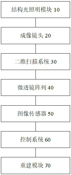
[0029] figure 1 It is a schematic structural diagram of a super-resolution scanning light field imaging system based on structured light illumination provided in Embodiment 1 of the present application.

[0030] like figure 1 As shown, the super-resolution scanning light fiel...


PUM


Abstract

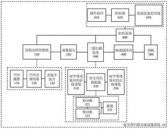
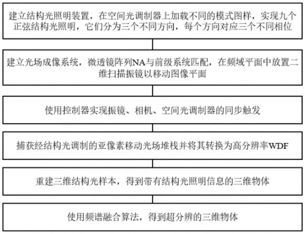
The invention provides a super-resolution scanning light field imaging system and method based on structured light illumination. The system comprises a structured light illumination module used for generating illumination modulation of a sine period, an imaging lens used for amplifying a target sample and imaging the target sample on an image plane of a two-dimensional scanning system, a two-dimensional scanning system used for rotating an optical path angle in a frequency domain plane, translating the image plane by sub-pixels, and meanwhile, matching a numerical aperture between an objective lens and a micro-lens array and amplifying or reducing the image plane, the micro lens array used for modulating different light beams on a rear focal plane, an image sensor used for recording a plurality of modulation images, a control system used for synchronously triggering the structured light illumination module, the two-dimensional scanning system and the image sensor; and a reconstruction module used for acquiring the plurality of modulation images recorded by the image sensor and realizing super-resolution three-dimensional imaging through a three-dimensional reconstruction algorithm and a frequency domain fusion algorithm. The system and method have the advantages of simple structure, low cost, suitability for living cell microscopic observation, multi-organelle interaction observation and the like.

Description

technical field [0001] The present application relates to the technical field of computational imaging, in particular to a super-resolution scanning light field imaging system and method based on structured light illumination. Background technique [0002] Optical resolution is limited by the diffraction limit, and two points that are very close in space cannot be resolved by the optical system. This resolution limitation, usually around 200nm, affects the observation effect of the microscopic system on biological tissue cells. For example, conventional optical microscopes cannot observe the clear internal structures of important organelles such as mitochondria and lysosomes. Researchers have been working hard to study methods of super-resolution microscopy. So far, related technologies mainly include the following imaging methods. [0003] The first method is based on fluorescence quenching stimulated emission depletion microscopy. By quenching the halo around the spot, ...

Claims


Application Information

Patent Timeline
Patent Type & Authority Applications(China)
IPC IPC(8): G01N21/64G02B21/00
CPCG01N21/6458G02B21/002G02B21/0076
Inventor 戴琼海卢志刘文辉吴嘉敏
Owner TSINGHUA UNIV
Learn More