
Color plating device for aerospace mold production

An aerospace and mold technology, applied in the direction of spraying devices, devices for coating liquid on the surface, spray booths, etc., can solve the problems of inconvenient use, coating thickness and uniformity control, etc., and achieve pollution prevention, good spraying effect, The effect of high design selectivity

Active Publication Date: 2021-10-12
JIANGSU RUIDE MACHINERY CO LTD
View PDF7 Cites 1 Cited by
  • Summary
  • Abstract
  • Description
  • Claims
  • Application Information

AI Technical Summary

Problems solved by technology

[0003] Existing aerospace molds need to be plated according to the style of the model when spraying, but the current spraying conditions are difficult to control the thickness and uniformity of the coating. A pressure-sensitive coating is disclosed in the prior art (CN201911227812.9) Intelligent automatic spraying system and spraying method. The system uses non-contact optical measurement technology to realize the recognition and acquisition of the three-dimensional contour of the model. The intelligent control terminal performs the design of the spraying path, spraying device posture, and flow rate, and outputs control signals to the model motion control device, intelligent The robot arm and the solenoid valve of the spraying device, in which the model motion control device can control the model to rotate, the intelligent robot arm drives the spraying device to move, and the solenoid valve of the spraying device controls the spraying action and flow rate, and automatically completes the spraying of pressure-sensitive paint on the surface of the model. There is technology to realize the unmanned spraying operation of paint, but this equipment can only be used for the spraying of single-color paint. When diversified spraying is required, the paint in the paint tank needs to be prepared and replaced, which is inconvenient to use. Therefore, we propose A color-plating device for aerospace mold production, which can automatically perform color-plating operations on target objects, and is convenient for popularization and use

Method used


Image

  • Color plating device for aerospace mold production
  • Color plating device for aerospace mold production
  • Color plating device for aerospace mold production

Examples


Embodiment 1

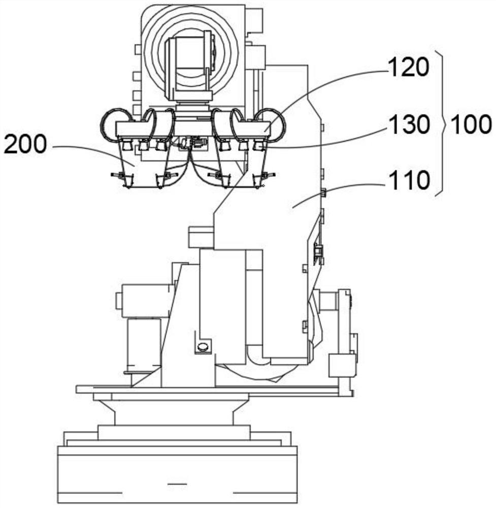
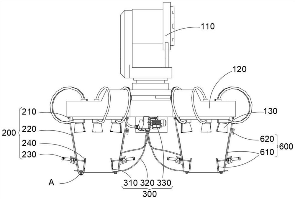
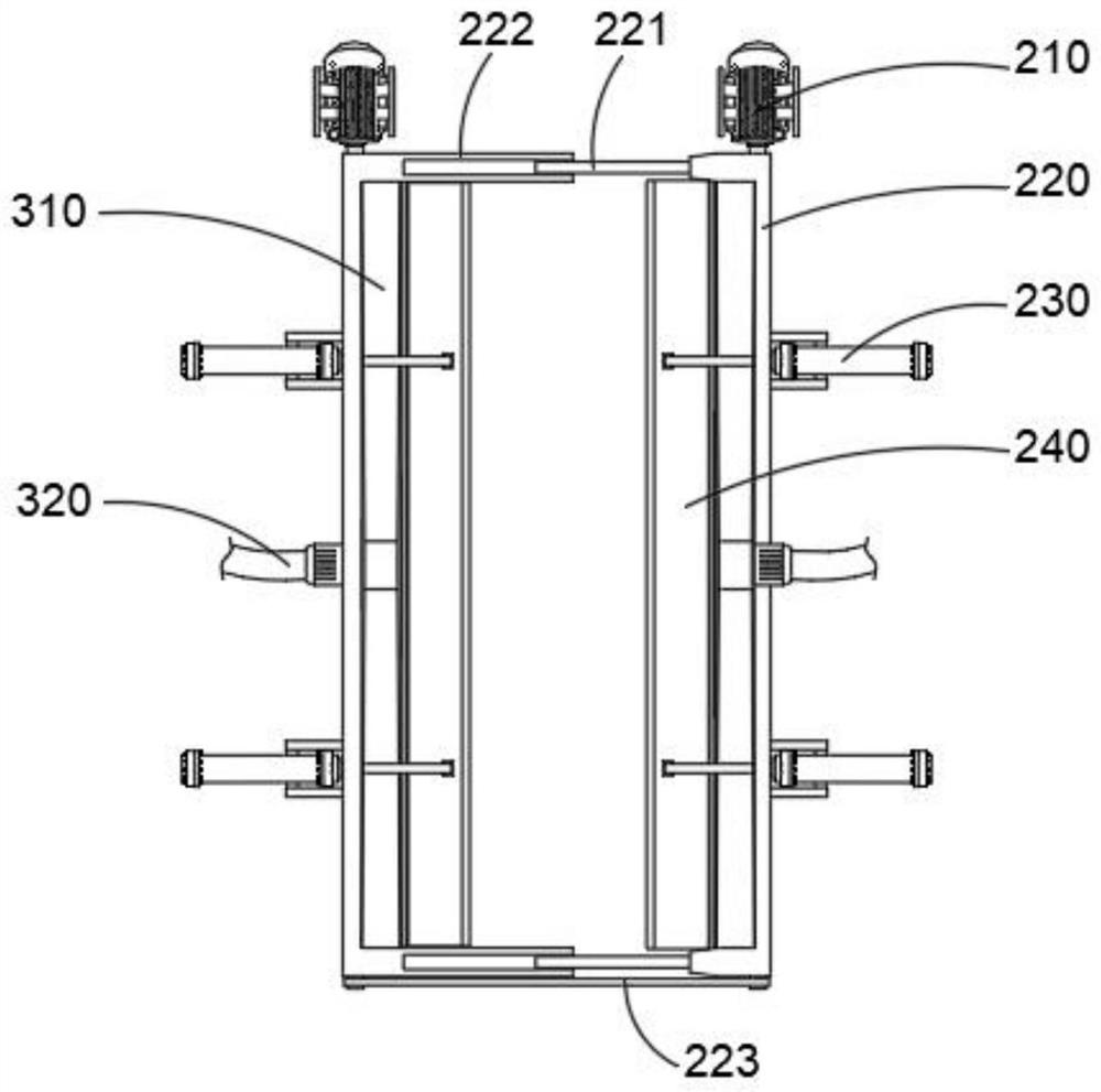
[0044] combine Figure 1-7As shown, the color plating device for aerospace mold production provided by the present invention includes: a spraying mechanism 100, an adjustment mechanism 200, a recycling mechanism 300, a pattern coating mechanism 400, a drying mechanism 500 and a heating mechanism 600, and the spraying mechanism 100 includes a The mechanical arm 110 of the spraying operation, the installation platform 120 connected to the driving end of the mechanical arm 110, and the spraying head 130 installed on the installation platform 120 for spraying materials. The head 130 is an adjustable spray head, which is convenient for different colors of paint to generate the required colors. The position and orientation of the spray head 130 can be automatically controlled through the mechanical arm 110, which is convenient for the overall spraying of the model, and the installation platform 120 is used to accommodate multiple groups of spray heads 130 The hollow plate structure ...

Embodiment 2

[0052] combine figure 2 As shown, on the basis of Embodiment 1, the heating mechanism 600 is arranged on the adjustment baffle 220 and the liquid storage tank 310 for heating and collecting the paint. The heating mechanism 600 includes The heating patch 610 on the inner wall and the heater 620 electrically connected to the heating patch 610, through the heating mechanism 600, the paint to be in contact with the adjustment baffle 220 can fall on the heating patch 610, and the heater 620 is used to control the heating patch 620. The sheet 610 continues to generate heat, so that the paint after contact will not solidify, but flows into the interior of the liquid storage tank 310 along the heating patch 610, further improving the collection effect of the paint. Of course, the interior of the liquid storage tank 310 can also be provided with The heating patch 610 has the same structure as the heating element to prevent the paint from solidifying before being discharged, which is m...

Embodiment 3

[0055] combine figure 2 and 6 As shown, in the above embodiment, the drying mechanism 500 is installed on the coating mechanism 400 to pre-dry the spraying position, and the surface of the model after spraying can be dried by the heating mechanism 600, so that the paint can be dried quickly, preventing Contamination and deformation caused by foreign objects falling on it or tilting movement to ensure the stability of the sprayed surface.

[0056] Specifically, the drying mechanism 500 includes a box seat 510 arranged outside the winding drum 430, a drying heater 520 installed on the box seat 510 for radiant heating, and a material baffle plate connected to the box seat 510 and located inside the drying heater 520. 530, the box base 510 is used to protect the structure of the reel 430 on the coating mechanism 400. It is a detachable structure, which is convenient for the setting of the drying mechanism 500 during installation. The drying heater 520 is a radiation dryer, which...


PUM


Abstract

The invention belongs to the technical field of spraying equipment, and particularly relates to a color plating device for aerospace mold production. The device comprises a spraying mechanism, an adjusting mechanism, a recycling mechanism, a pattern spraying mechanism, a drying mechanism and a heating mechanism. The spraying mechanism comprises a mechanical arm used for automatic spraying operation, a mounting platform connected to the driving end of the mechanical arm and spraying heads mounted on the mounting platform and used for spraying materials. The adjusting mechanism comprises a first motor installed on the mounting platform. According to the color plating device, through the adjusting mechanism, paint sprayed out of the multiple spraying heads can be intensively mixed and then sprayed to a model, paint mixing color plating operation is achieved, paint does not need to be replaced, paint can be taken or used in a mixed manner from multiple sets of paint tanks connected with the spraying heads, and sprayed inner and outer openings can be adjusted; and therefore, the spraying area and thickness are adjusted, the spraying effect is better, the device can be lifted for use when not used, and the practicability is higher.

Description

technical field [0001] The invention relates to the technical field of spray coating equipment, in particular to a color coating device for aerospace mold production. Background technique [0002] Spraying, also known as thermal spraying, is a technology that sprays molten spraying materials on the surface of metal, alloy, plastic, ceramics and other workpieces with a power device to form a complete covering layer. The spraying material can be metal or non-metallic. The heat source melts or softens it, relying on the power of the heat source itself or an external compressed air flow, the molten droplets are atomized or pushed into sprayed beams, which are sprayed onto the surface of the substrate at a certain speed to form a coating. After the workpiece is sprayed, it can improve its Anti-corrosion, heat resistance and wear resistance, increase its thickness or repair size, etc. At the same time, some spraying equipment is used to spray logos, patterns or paintings, so as to...

Claims


Application Information

Patent Timeline
IPC IPC(8): B05B13/04B05B12/32B05B14/00B05B16/20B05B12/16B05D3/02
CPCB05B13/0431B05B12/32B05B14/00B05B16/20B05B12/16B05D3/0254Y02P70/10
Inventor 李圣奕宋文杰吕兆海宋文盛
Owner JIANGSU RUIDE MACHINERY CO LTD
Learn More