
Blade perfusion process method and perfusion system

A process method and blade technology, applied to other household appliances, household appliances, household components, etc., can solve the problems of dry yarn, semi-dry yarn, pouring outflanking, and low operating time, so as to save consumption, improve stability, The effect of protecting the environment

Pending Publication Date: 2021-10-12
SHANGHAI ELECTRIC WIND POWER GRP CO LTD
View PDF5 Cites 0 Cited by
  • Summary
  • Abstract
  • Description
  • Claims
  • Application Information

AI Technical Summary

Problems solved by technology

However, polyurethane is sensitive to water and is irritating to human skin. Therefore, polyurethane has higher requirements for the sealing of the perfusion system, and the viscosity and operating time of polyurethane resin are much lower than epoxy resin, which is easy to cause outflanking of perfusion. This will lead to the formation of defects such as dry yarn and semi-dry yarn. It takes a short time to complete the vacuum infusion and ensure the quality of the infusion, and has higher requirements for the infusion operation and the layout of the flow channel system.

Method used


Image

  • Blade perfusion process method and perfusion system
  • Blade perfusion process method and perfusion system
  • Blade perfusion process method and perfusion system

Examples


Embodiment 1

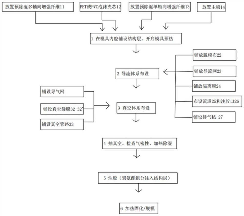
[0045] Polyurethane vacuum infusion process such as figure 2 Shown:

[0046] 1) Lay the structural layer in the inner cavity of the mold, open the mold for preheating:

[0047]The laying structure layer includes: pre-dehumidification multi-axial glass fiber fabric 11 , low-water lightweight sandwich material 12 , pre-dehumidification uniaxial reinforcement fiber 13 , and main beam 14 . Wherein, the low-moisture lightweight sandwich material 12 is preferably PVC or PET.

[0048] The specific laying method is: first lay 2-10 layers of multi-axial fiberglass fabrics on the blade body and tip area, in this example, 3 layers are laid, and 20-100 layers of pre-dehumidified multi-axial fiberglass fabrics are laid on the blade root area Fiberglass fabric 11; then lay 10-50 layers of pre-dehumidification uniaxial reinforcing fiber 13 and then place main beam 14 on the multiaxial fiberglass fabric and lay PET foam board (low-moisture lightweight sandwich material in a conventional ma...

Embodiment 2

[0080] A blade infusion system is used for infusing epoxy resin into a blade mold, and the system includes: a mold, a diversion system, and a vacuum system. The laying method and sequence of the mould, diversion system, and vacuum system are the same as in Example 1.

[0081] To sum up, the present invention discloses a blade vacuum infusion process method, in which guide nets are laid narrowly in other areas of the blade body, which has good technical effects. This method saves the amount of resin and the amount of guide net, avoids the defects of dry yarn or semi-dry yarn, improves the stability of blade forming, is conducive to protecting the environment, saving resources, and can reduce the pouring time. Glue injection for precise control.


PUM

PropertyMeasurementUnit
widthaaaaaaaaaa
pore sizeaaaaaaaaaa

Abstract

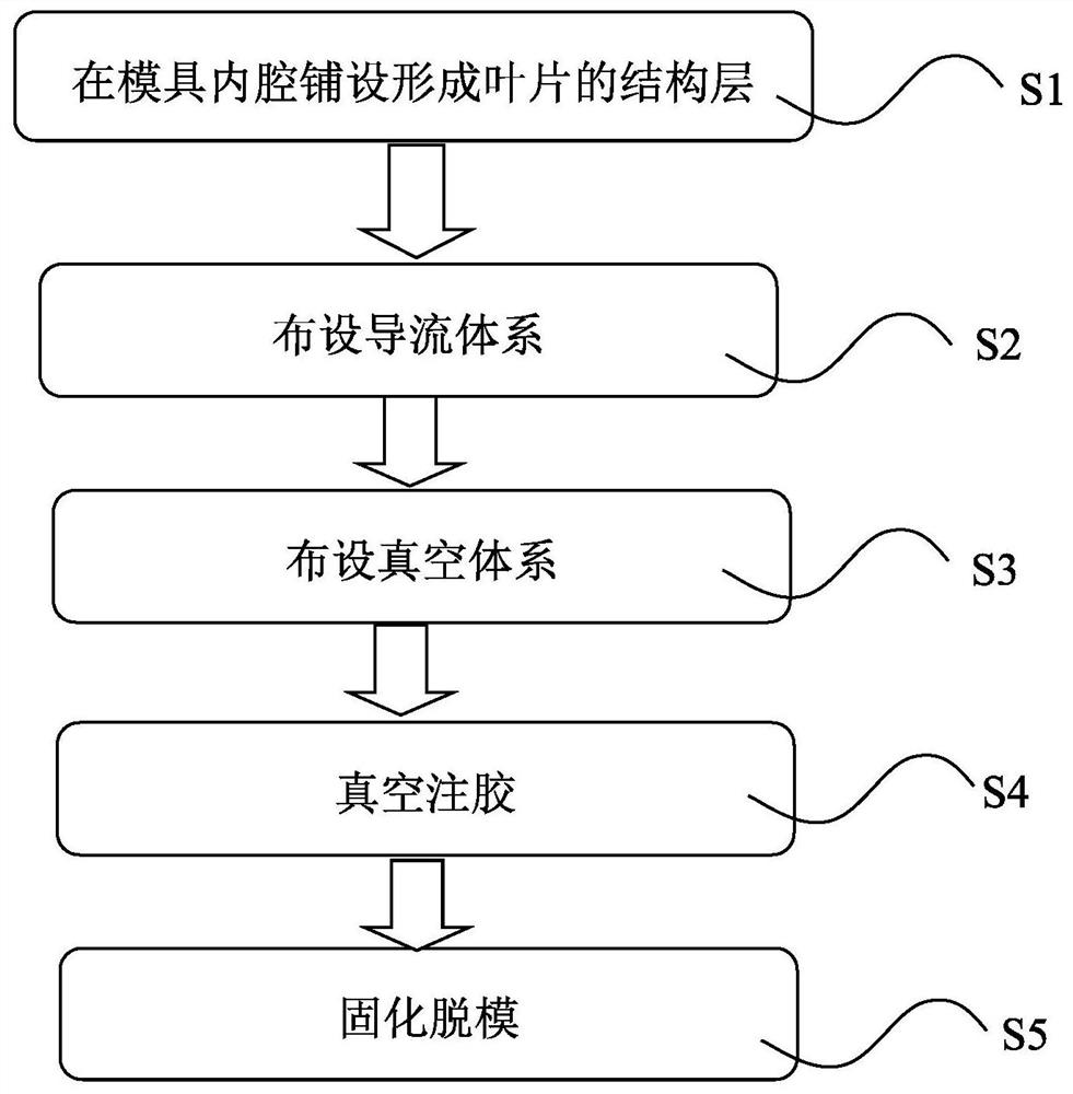
The invention discloses a blade perfusion process method and a perfusion system. The process method sequentially comprises the following steps that a structural layer for forming a blade is laid in an inner cavity of a mold; the mold comprises a blade root area, a blade body area and a blade tip area; a flow guide system is arranged above the structural layer, the flow guide system comprises a plurality of flow channels, the flow channels are arranged in the blade root area, the blade body area and the blade tip area respectively, and the flow channels in the blade root area and the flow channels in the blade body area are not in communication; a plurality of gel injection openings are formed in the flow channels; a vacuum system is arranged, and a vacuum environment is provided for the inner cavity of the mold; vacuum gel injecting is carried out; and curing and demolding are carried out. The risk of resin gel curing in the glue injection process can be reduced, the blade forming stability is improved, the contact with personnel and air outside water in the gel process is reduced, the use amount of resin and a flow guide net is saved, the environment is protected, resources are saved, the perfusion time is shortened, and gel injection of all areas is accurately controlled.

Description

technical field [0001] The invention relates to the technical field of wind power generation, in particular to a blade pouring process method and a pouring system. Background technique [0002] Wind energy is considered to be one of the cleanest and most environmentally friendly energy sources currently available, and as a result, wind turbines continue to be in demand. At present, epoxy resin is used in large quantities for fan blades, which are formed by vacuum assisted resin transfer molding (VARTM) technology. VARTM has the advantages of high production efficiency, high quality stability, high mechanical strength, less resin consumption and environmental friendliness. . Due to the high viscosity of epoxy resin, larger channels are required to ensure the dispersion speed of the resin. The resin remaining in the diversion tube and the diversion net is removed after solidification and becomes waste, which will cause cost waste and environmental pollution. [0003] Fan bl...

Claims


Application Information

Patent Timeline
Patent Type & Authority Applications(China)
IPC IPC(8): B29C70/48B29C70/54B29L31/08
CPCB29C70/48B29C70/54B29L2031/085
Inventor 王国军齐志攀白宏伟
Owner SHANGHAI ELECTRIC WIND POWER GRP CO LTD
Learn More