A calibration method, device and computer equipment for a three-dimensional laser scanning system

A scanning system and three-dimensional laser technology, applied in the computer field, can solve the problems of poor calibration parameters, complex calculations, easy to fall into local optimum, etc., and achieve the effect of accurate results, high efficiency and simple operation

Active Publication Date: 2021-11-23
深圳广成创新技术有限公司
View PDF13 Cites 0 Cited by
  • Summary
  • Abstract
  • Description
  • Claims
  • Application Information

AI Technical Summary

Problems solved by technology

However, these methods have the following problems: the production accuracy of the calibrated object is high, multiple pictures are required, special auxiliary platforms (such as displacement platforms) are required, the calculation is complicated, and it is easy to fall into the local optimum
[0004] To sum up, there are mainly two problems with the existing methods: 1) There are many problems in the calibration process that need attention, such as the production of the calibration board, the location of the calibration process, the number of calibration images, etc., if the experience is insufficient , it is easy to get poor calibration parameters; 2) The calibration parameter optimization of the existing method is based on the minimum error of the 2D image coordinates of the detected corner point to the calibration plane, while the actual measurement is based on the three-dimensional coordinate distance The scale is standard, so the calibration optimization error is difficult to reflect the actual calibration parameters

Method used


Image

  • A calibration method, device and computer equipment for a three-dimensional laser scanning system
  • A calibration method, device and computer equipment for a three-dimensional laser scanning system
  • A calibration method, device and computer equipment for a three-dimensional laser scanning system

Examples


Embodiment Construction

[0051] In order to make the technical problems, technical solutions and beneficial effects solved by the embodiments of the present invention clearer, the embodiments of the present invention will be further described in detail below in conjunction with the accompanying drawings and the embodiments. It should be understood that the specific embodiments described here are only used to explain the present invention, not to limit the present invention.

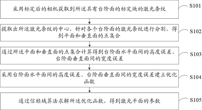
[0052] refer to figure 1 , which shows a flow chart of the steps of an embodiment of a calibration method for a three-dimensional laser scanning system according to an embodiment of the present invention. The three-dimensional laser scanning system includes a camera, a laser emitter, and a calibration block with a stepped surface, and may specifically include the following steps :

[0053] Step 101, using a calibrated camera to acquire the laser stripes of the calibration block with a stepped surface;

[0054] In the embodiment o...


PUM


Abstract

Embodiments of the present invention provide a calibration method, device, and computer equipment for a three-dimensional laser scanning system. The three-dimensional laser scanning system includes a camera, a laser transmitter, and a calibration block with a stepped surface, including: using the calibrated camera to acquire The laser stripes of the calibration block with the step surface; extract the center of the laser stripe, and divide the laser stripes of each step surface to obtain the point set of the plane and the vertical plane; through the point set of the plane and the vertical plane Calculate the height error between the horizontal planes of the step surface and the width error between the vertical surfaces of the step surface; adopt the height error between the horizontal planes of the step surface and the width error between the vertical surfaces of the step surface to establish an optimization function; solve the optimization function by the trust region algorithm, Get the parameters of the laser plane. Calibration and parameter optimization of the line laser three-dimensional measurement system can be completed using only one step surface, with simple operation, high efficiency, suitable for on-site operation, and accurate results.

Description

technical field [0001] The invention relates to the field of computer technology, in particular to a calibration method for a three-dimensional laser scanning system, a calibration device for a three-dimensional laser scanning system, a computer device and a storage medium. Background technique [0002] Line laser 3D reconstruction based on laser and camera is the most important method of non-contact 3D measurement widely used at present. This technology is based on the principle of triangulation in stereo vision, and projects a laser plane onto the object through line laser. , using the calibrated camera to obtain the laser plane stripes on the object, and the three-dimensional coordinates of the target object illuminated by the laser plane can be obtained through the triangulation ranging principle. The most important and first step in online laser measurement is calibration. The calibration is further divided into camera calibration and laser plane calibration. Among th...

Claims


Application Information

Patent Timeline
Patent Type & Authority Patents(China)
IPC IPC(8): G01B11/25G01C25/00G06T7/80
CPCG01B11/254G01B21/042G01C25/00G06T7/80
Inventor 宋展叶于平
Owner 深圳广成创新技术有限公司
Why Eureka
Try Eureka