
Optical fiber connector

A technology of optical fiber connectors and optical fiber components, applied in the direction of light guides, optics, instruments, etc., can solve the problems of reducing the protection of wires by internal optical fibers, product failure, and reducing strength

Pending Publication Date: 2021-10-12
连讯通信(天津)有限公司
View PDF0 Cites 0 Cited by
  • Summary
  • Abstract
  • Description
  • Claims
  • Application Information

AI Technical Summary

Problems solved by technology

In addition, the combined structure of the fiber optic housing B and the ferrule C1 is a hexagonal and tapered engagement method. Due to the wear of the tool during metal processing, it is difficult to control the accuracy of the angle of the metal parts, resulting in the failure of the product to achieve high-precision docking.
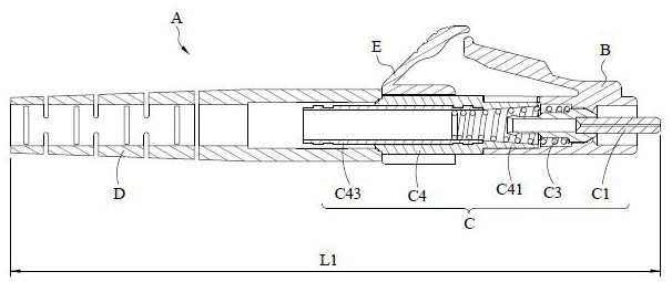
[0006] The total length L1 of the existing optical fiber connector A is too long to meet the size and use requirements in the 5G network cabinet
When rigidly assembled, it will cause early damage to the locking point and the locking groove of the main mechanical strength, reducing the strength
Open the crimping method of the wire sheath to reduce the protection of the wire sheath for the internal optical fiber. At the same time, the wire sheath is easily broken during use, resulting in product failure
The ferrule C1 part of the riveted ferrule adopts the combination of hexagon and taper. Due to the high degree of difficulty in processing precision, the finished LC connector cannot achieve high-precision docking

Method used


Image

  • Optical fiber connector
  • Optical fiber connector
  • Optical fiber connector

Examples


Embodiment Construction

[0079] In order to make the purpose, technical features and advantages of the present invention better understood by those skilled in the art and to implement the present invention, the technical features and implementation methods of the present invention are explained in the following description in conjunction with the accompanying drawings, and The preferred embodiments are listed for further description, but the following descriptions of the embodiments are not intended to limit the present invention, and the following diagrams are used to express the schematic representations related to the characteristics of the present invention.

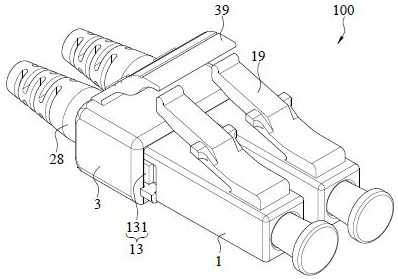
[0080] Please also see Figure 3 to Figure 4 , image 3 It is a schematic diagram of the appearance (1), Figure 4 For the decomposition diagram. It is an embodiment of a fiber optic connector. In this embodiment, the fiber optic connector 100 includes a plurality of butt joint housings 1 and fiber optic components 2, but it is not limited...


PUM

PropertyMeasurementUnit
Lengthaaaaaaaaaa
Lengthaaaaaaaaaa
Lengthaaaaaaaaaa

Abstract

An optical fiber connector of the present invention comprises a butt joint shell and an optical fiber assembly. The butt-joint shell internally comprises a cavity, one end of the butt-joint shell is provided with an interface communicated with the cavity, and the two side walls of the butt-joint shell comprise a plurality of buckling parts adjacent to the interface. The optical fiber assembly is fixed in the cavity and comprises a sleeve, the length of the sleeve is 6.25 mm-10.25 mm, and the sleeve comprises a block body assembled into the interface. The total length of the optical fiber connector is 30 mm-35 mm, buckling parts are formed at the two sides of the block body, and the buckling parts are correspondingly buckled to the buckling parts.

Description

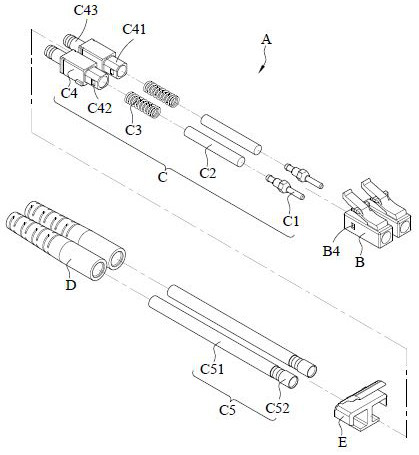
technical field [0001] The invention relates to an optical fiber connector. Background technique [0002] Optical fiber is a light transmission tool, and the general optical fiber connection device is a female adapter (Adapter) with a male optical fiber connector inserted at both ends as a docking, so as to achieve the purpose of clamping and data transmission. [0003] see figure 1 and figure 2 as shown, figure 1 It is a schematic diagram of the decomposition of the prior art, figure 2 It is a side view cross-sectional schematic diagram of the prior art. The existing optical fiber connector A includes an optical fiber housing B, an optical fiber assembly C, a boot D, and a pressing piece E. The optical fiber assembly C includes a ferrule C1, a core tube C2, a spring C3, a sleeve C4, and a sleeve from the front end to the rear end. The tube C5 and the ferrule C1 protrude from one end of the optical fiber housing B, and the tail sleeve D is fixed on the other end of th...

Claims


Application Information

Patent Timeline
IPC IPC(8): G02B6/38
CPCG02B6/3833G02B6/3821
Inventor 崔洋洋常艳梅楚广虎
Owner 连讯通信(天津)有限公司
Learn More