Ultrasonic positioning sampling puncture system

A technology of ultrasonic positioning and puncture needles, which is applied in puncture needles, stereotaxic surgical instruments, inoculation and ovulation diagnosis, etc. It can solve the problem that the sample tissue cannot be extracted by conventional means, the samples obtained cannot meet the needs, and the puncture needles are difficult to take successfully. To achieve stable and controllable operation process, reduce dependence on experience, and facilitate rehabilitation

Pending Publication Date: 2021-10-19
浙江壹康普麦医疗科技有限公司
View PDF2 Cites 0 Cited by
  • Summary
  • Abstract
  • Description
  • Claims
  • Application Information

AI Technical Summary

Problems solved by technology

In the process of puncture sampling, sometimes samples are not obtained very smoothly every time. Some samples are too hard to be extracted by conventional means, and even the samples obtained cannot meet the needs. The controllability of existing puncture equipment is poor. After puncture sampling, the puncture needle needs to be taken out and the sample is retained. When puncture sampling is required again, the aforementioned process is repeated, which greatly prolongs the patient's suffering time. Therefore, a device that does not need to be pulled out of the body to accurately grab samples has been developed. has great practical significance
[0003] In the prior art, we can see that the published document CN212913323U is a multifunctional hemodialysis puncture needle, which relates to the field of puncture needle technology. To determine the specific nature of the tissue, the texture of the tissue is relatively hard, and it is difficult to successfully use a general puncture needle, because some tissues may adhere to other tissues, and it is impossible to sample successfully through simple negative pressure extraction methods. Based on this problem Application to design puncture needle with sharp grip

Method used


Image

  • Ultrasonic positioning sampling puncture system
  • Ultrasonic positioning sampling puncture system
  • Ultrasonic positioning sampling puncture system

Examples


Embodiment

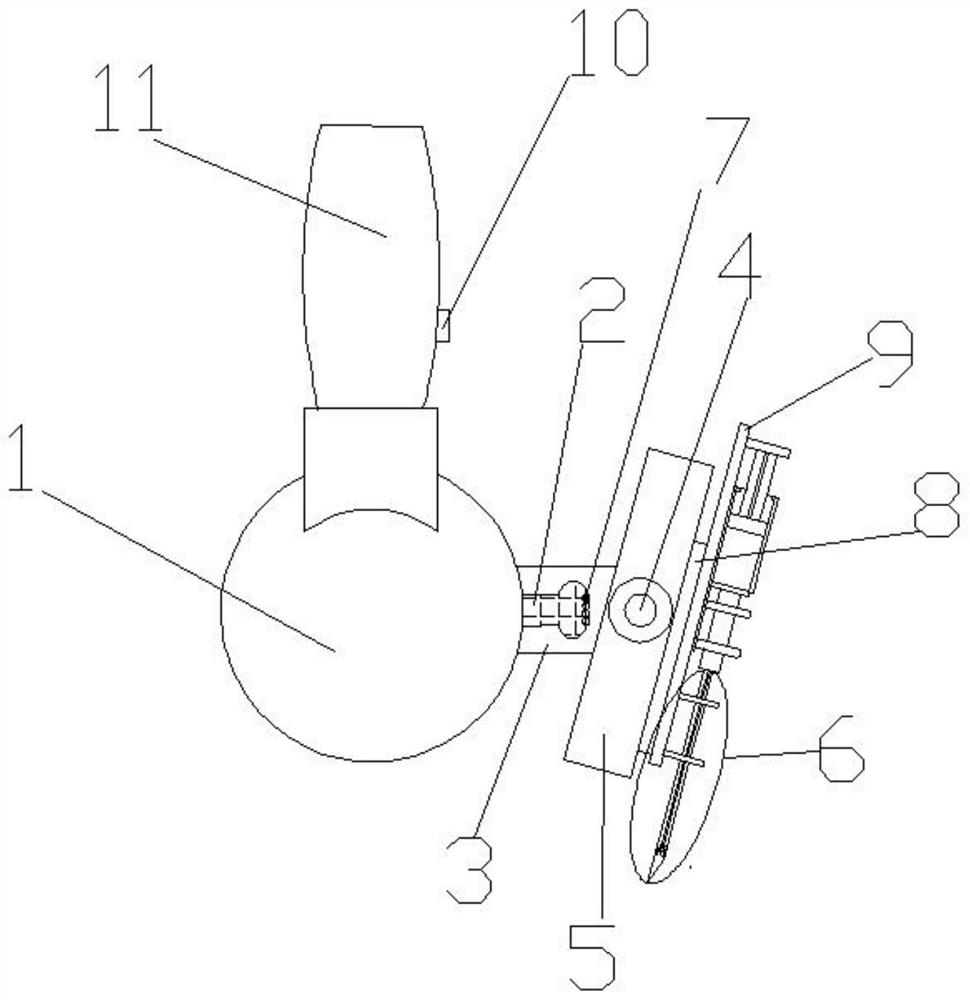
[0032] Example: see Figure 1-3 as shown,

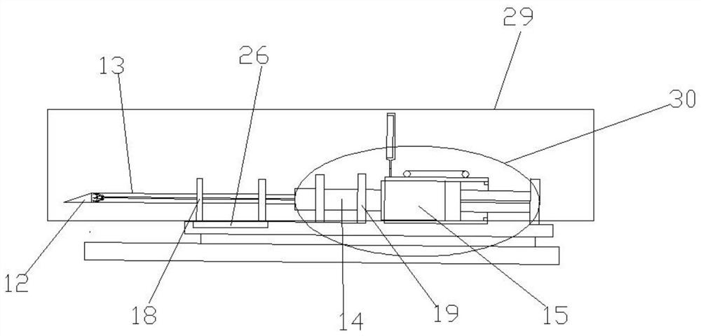
[0033]An ultrasonic positioning and sampling puncture system, comprising an ultrasonic probe 1, the right side of the ultrasonic probe 1 is fixedly connected to an external fixed end 2, the external fixed end 2 is provided with a connecting body 3, the connecting body 3 is fixedly connected to a turret 5, and the center of the turret 5 is The position is provided with a rotating shaft 4, and the right side of the turret 5 is fixedly connected with a slide rail 8, the rotating shaft 4 is connected with a deceleration drive motor and rotates axially, the right side of the sliding rail 8 is fixedly connected with a moving seat 9, and the right side of the moving seat 9 A sampling puncture needle 29 is fixedly connected, and the sampling puncture needle 29 includes a needle tube 30. The front end of the needle tube 30 is movably connected with a puncture needle body 6, and the puncture needle body 6 moves along its length on the turret. ...


PUM


Abstract

The invention discloses an ultrasonic positioning sampling puncture system which comprises an ultrasonic probe, the right side of the ultrasonic probe is fixedly connected with an externally-hung fixed end, a handle is arranged at the upper end of the ultrasonic probe, a control switch is arranged on one side of the handle, a connecting body is arranged outside the externally-hung fixed end and fixedly connected with a rotating frame, and a rotating shaft is arranged in the center of the rotating frame. The right side of the sliding rail is fixedly connected with a moving seat, the right side of the moving seat is fixedly connected with a sampling puncture needle, the sampling puncture needle comprises a needle tube, the front end of the needle tube is movably connected with a puncture needle body, and the puncture needle body is pushed to move on the rotating frame in the length direction of the rotating frame; a grabbing mechanism is arranged in the puncture needle body and comprises a grabbing hand and a grabbing hand connecting pipe, the advantages of being high in target accuracy, good in safety and easy to operate can be achieved, and under the assistance of a computer, the target can be rapidly determined, the positioning process is simplified, the operation difficulty is lowered, dependence on the experience of an operator is reduced, and the working efficiency is improved.

Description

technical field [0001] The invention relates to the field of medical devices, in particular to an ultrasonic positioning sampling puncture system. Background technique [0002] In the field of medical devices, pathological diagnosis is the gold standard of medicine. In order to obtain prepared samples, ultrasound is often used for positioning. Ultrasonic puncture sampling requires manual operation by professional medical staff, and maintains a steady movement to complete accurate puncture. Therefore, the success rate of puncture sampling is related to the technical level of the operator. Accurate sampling helps to quickly obtain accurate pathological information and timely treat patients. To develop the correct treatment plan, and to ensure the success rate of puncture, it is necessary to improve the technical level of medical staff, but the technical training process takes a long time, and cannot effectively solve the technical gap. On this basis, from the perspective of me...

Claims


Application Information

Patent Timeline
IPC IPC(8): A61B10/02A61B17/34A61B17/3209A61B90/14
CPCA61B10/0266A61B10/0283A61B17/34A61B17/3403A61B17/3209A61B90/14A61B2017/3413A61B2017/3409A61B2017/320064
Inventor 不公告发明人
Owner 浙江壹康普麦医疗科技有限公司
Why Eureka
Try Eureka