Steel structure solar curtain wall

A solar energy and steel structure technology, applied in the field of solar curtain wall, can solve the problems of weak wind pressure resistance, low service life, easy to be damaged, etc., and achieve the effect of strong wind pressure resistance, long service life and good stability

Active Publication Date: 2021-10-19
ZHEJIANG HETE PHOTOELECTRICITY CO LTD
View PDF10 Cites 1 Cited by
  • Summary
  • Abstract
  • Description
  • Claims
  • Application Information

AI Technical Summary

Problems solved by technology

[0005] In order to solve the problems of poor overall structural stability, weak wind pressure resistance, easy damage, and low service life in related technologies, the purpose of this application is to provide a steel structure solar curtain wall

Method used


Image

  • Steel structure solar curtain wall
  • Steel structure solar curtain wall
  • Steel structure solar curtain wall

Examples


Embodiment 1

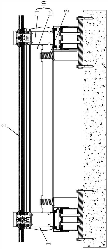
[0046] refer to figure 1 , is a steel structure solar curtain wall disclosed in the present application, comprising a fixed frame 1 and a solar curtain wall panel 2, the solar curtain wall panel 2 is fixedly connected in the fixed frame 1, and the fixed frame 1 is fixedly connected to the building wall by bolts. The fixed frame 1 includes columns 11 and crossbeams 12. The beams 12 are fixedly connected between adjacent columns 11 by aluminum alloy corner screws, thereby forming a curtain wall installation unit 10, which is used to fix the solar curtain wall panel 2.

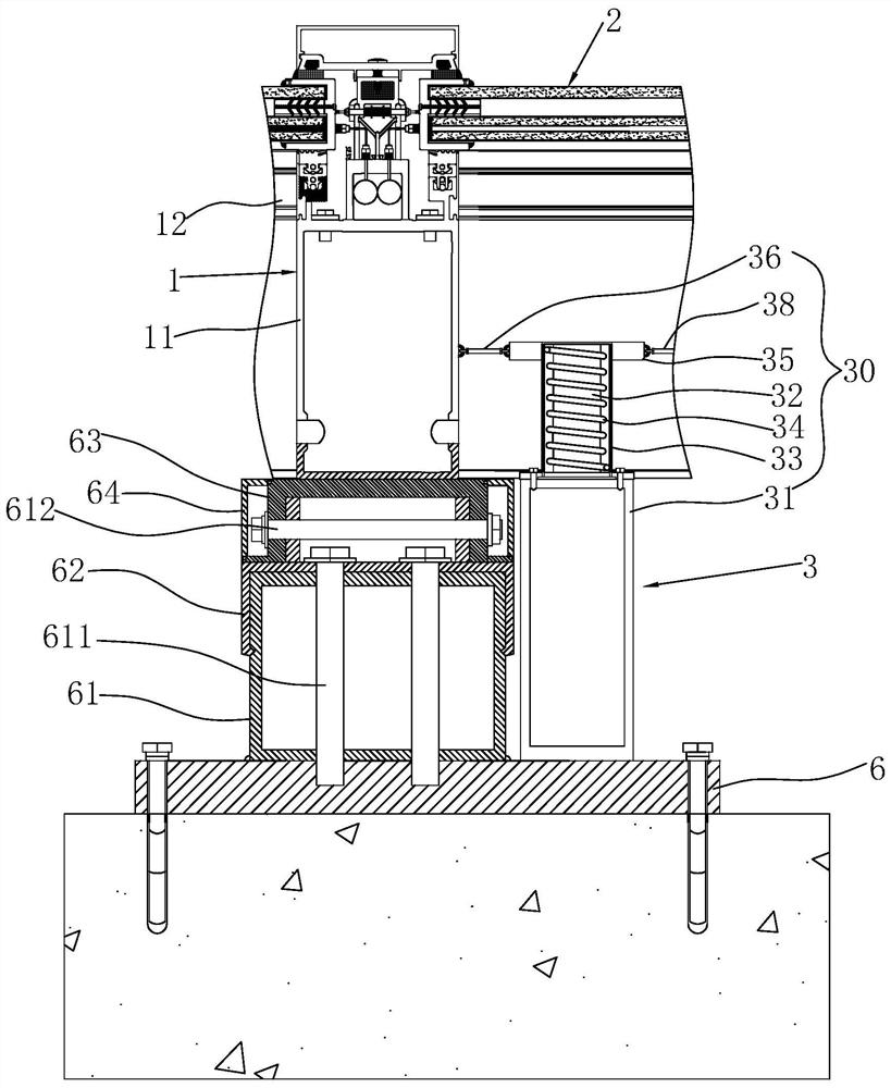
[0047] refer to figure 2 , the specific installation structure of the fixed frame 1 is as follows: the building wall is fixedly connected with a cushion steel plate 6 through expansion screws. In order to ensure the stability of the connection, the lower surface of the cushion steel plate 6 is first coated with silicone rubber adhesive and then used for expansion screws. Fixed connection to the building wall. ...

Embodiment 2

[0067] The difference between embodiment 2 and embodiment 1 is: refer to Figure 10 The balance component 340 is fixedly connected to the upper circumferential direction of the first round tube 33 , and the balance component 340 includes a first ring 35 , a first elastic cord 36 , and a second elastic cord 37 . The first circular ring 35 is welded on the outer wall of the upper end of the first round pipe 33 , and a first elastic rope 36 and a second elastic rope 37 are respectively hinged on the outer wall of the first circular pipe 35 . The angle formed by the first elastic cord 36 and the second elastic cord 37 is 90°.

[0068] refer to Figure 10 One end of the first elastic cord 36 is hinged to the outer wall of the first ring 35 and the other end is hinged to the middle of the side of the column 11 . One end of the second elastic cord 37 is hinged to the outer wall of the first ring 35 and the other end is hinged to the side middle of the beam 12 . The first elastic c...


PUM


Abstract

The invention relates to the technical field of solar curtain walls, in particular to a steel structure solar curtain wall. The steel structure solar curtain wall comprises a fixed frame which is fixedly connected to a building wall body and a solar curtain wall plate which is fixedly connected to the fixed frame, the fixed frame comprises stand columns and cross beams fixedly connected between the adjacent stand columns, a plurality of curtain wall mounting units used for assembling the solar curtain wall plate are formed between the adjacent stand columns under the separation of the cross beams, and a buffer mechanism used for releasing internal stress is arranged in each curtain wall mounting unit. According to the steel structure solar curtain wall, the overall structural stability is good, the wind pressure resistance is high, and the service life is long.

Description

technical field [0001] The present application relates to the technical field of solar curtain walls, in particular to a steel structure solar curtain wall. Background technique [0002] With the increase of the world's population, the energy gap is getting bigger and bigger, and the resource problem has become the main contradiction restricting the development of the world today. Among them, fossil energy is still the main energy source today, but its reserves are limited, and it is bound to be exhausted one day in the future. In this environment, scientists from all over the world are vigorously developing renewable energy sources, such as solar energy. At present, solar photovoltaic applications have developed rapidly, and different applications are being tried in various industries. As an industrialized energy-saving and emission-reducing product, solar curtain wall has been used in the curtain walls of various buildings. The photovoltaic modules in the solar curtain w...

Claims


Application Information

Patent Timeline
Patent Type & Authority Applications(China)
IPC IPC(8): E04B2/88E04B2/96E04B1/76E04B1/82H02S20/26F24S20/66F24S25/632
CPCE04B2/885E04B1/7608E04B1/8227H02S20/26F24S20/66F24S25/632Y02E10/47Y02B10/20
Inventor 张群芳宋睿
Owner ZHEJIANG HETE PHOTOELECTRICITY CO LTD
Why Eureka
Try Eureka