
Automatic test system for inertial measurement product

A technology of automated testing and inertial measurement, applied in the field of inertial measurement, can solve the problems of lack of flexibility, high demand for software changes and maintenance, single function, etc., to reduce control complexity, facilitate changes and maintenance, and improve test efficiency.

Pending Publication Date: 2021-10-19
BEIJING AEROSPACE TIMES OPTICAL ELECTRONICS TECH
View PDF0 Cites 0 Cited by
  • Summary
  • Abstract
  • Description
  • Claims
  • Application Information

AI Technical Summary

Problems solved by technology

Environmental stress tests often take hours or days, and require manual real-time monitoring of product status and regular power on and off, data collection and other operations; functional and performance tests require testers to have proficient operating levels and high test data Interpretation ability, wrong operation or interpretation will cause repeated tests and seriously delay the production progress. Therefore, in order to ensure the correctness and effectiveness of the test, it is often necessary to invest more manpower and time costs
[0003] At present, the existing automated test systems for inertial measurement products mainly focus on the reliability and correctness of data collection, and their functions are relatively single. This is mainly because inertial measurement products involve a variety of functions, performances and test environments. The test method is complex and changeable, the basis for judging the output data of the inertial instrument is not easy to determine, and it is difficult to realize automated testing
In addition, the complexity of test software programming will increase with the increase of its integrated functions, and the demand for software changes and maintenance is high, resulting in a lack of flexibility in the application of complex test items involved in inertial measurement products, which is not conducive to automated test software and System promotion and development

Method used


Image

  • Automatic test system for inertial measurement product

Examples


Embodiment 1

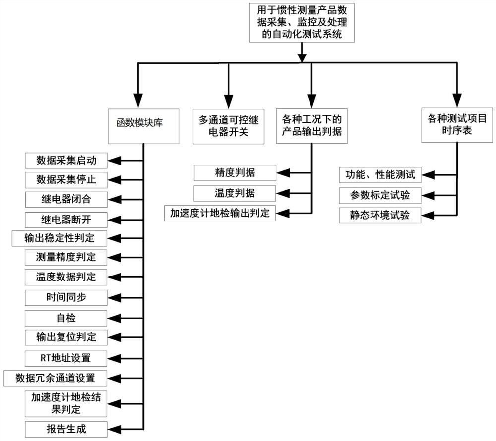
[0065] Such as figure 1 As shown, the specific implementation of the embodiment of the present invention can be divided into: a power supply, a relay module, an execution module, a function module library, and a sequence control module; the power supply includes a working power supply and a temperature control power supply;

[0066] The relay module of the embodiment is developed based on the SRD-12VDC-SL-C chip, and the 10 relay switches are respectively used to replace the following mechanical switches: working power switch, temperature control power switch, reset switch, reset block switch, RT1 address strobe switch, RT2 address strobe switch, RT3 address strobe switch, X accelerometer ground detection current switch, Y accelerometer ground detection current switch, Z accelerometer ground detection current switch.

[0067] The function module library includes sub-function module single-step operation functions and relay operation functions;

[0068] The single-step operati...


PUM


Abstract

The invention relates to an automatic test system for data acquisition, monitoring and processing of an inertial measurement product. A multi-channel programmable control relay module is designed to replace a mechanical switch for controlling the on-off of a power supply or a signal path of the inertial measurement product; program codes of single-step operations such as relay control, data acquisition control, data judgment, time synchronization, self-inspection, reset, RT address gating and accelerometer ground inspection data interpretation are written and packaged into sub-function module single-step operation functions respectively, the sub-function module single-step operation functions only need to be arranged according to specific test items, and therefore, automatic operation of single-item or multi-item testing can be achieved, new construction, change and maintenance of the system testing process are more convenient, the automation of the testing process is achieved, production efficiency is improved, meanwhile, labor cost is saved, and the possibility that testing fails and even products are damaged due to manual operation or manual interpretation errors is reduced.

Description

technical field [0001] The invention belongs to the technical field of inertial measurement and relates to a test system for inertial measurement products, in particular to an automatic test system for data collection, monitoring and processing of inertial measurement products. Background technique [0002] Inertial measurement products are key devices for sensitive carrier angular velocity and linear acceleration to complete navigation and guidance. The production and use of such products usually involve complex functional, performance and environmental stress tests. Environmental stress tests often take hours or days, and require manual real-time monitoring of product status and regular power on and off, data collection and other operations; functional and performance tests require testers to have proficient operating levels and high test data Interpretation ability, wrong operation or interpretation will cause repetition of the test and seriously delay the production pro...

Claims


Application Information

Patent Timeline
Patent Type & Authority Applications(China)
IPC IPC(8): G01C25/00
CPCG01C25/005
Inventor 杨鹏雷剑王宁王公伯李珍珍李旭晟
Owner BEIJING AEROSPACE TIMES OPTICAL ELECTRONICS TECH
Learn More