Special battery heat dissipation device for new energy automobile

A technology for new energy vehicles and heat dissipation devices, which is applied in secondary batteries, battery pack components, circuits, etc., to achieve the effect of improving work capacity, accelerating heat dissipation, and reducing heat loss

Inactive Publication Date: 2021-10-19
NINGDE NORMAL UNIV
View PDF0 Cites 0 Cited by
  • Summary
  • Abstract
  • Description
  • Claims
  • Application Information

AI Technical Summary

Problems solved by technology

cause a lot of heat

Method used


Image

  • Special battery heat dissipation device for new energy automobile
  • Special battery heat dissipation device for new energy automobile
  • Special battery heat dissipation device for new energy automobile

Examples


Embodiment 1

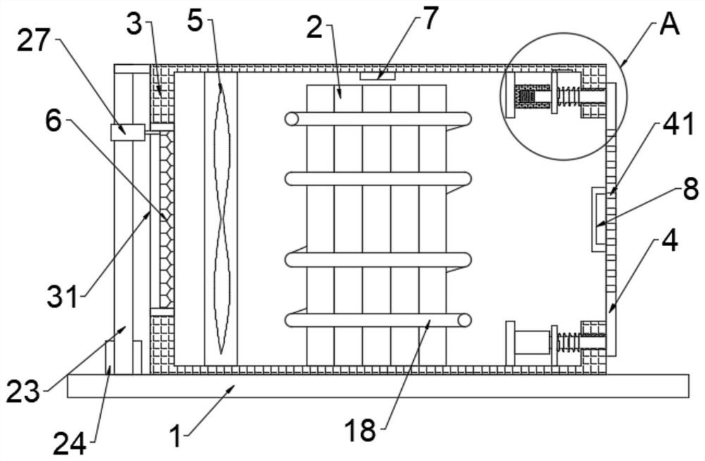
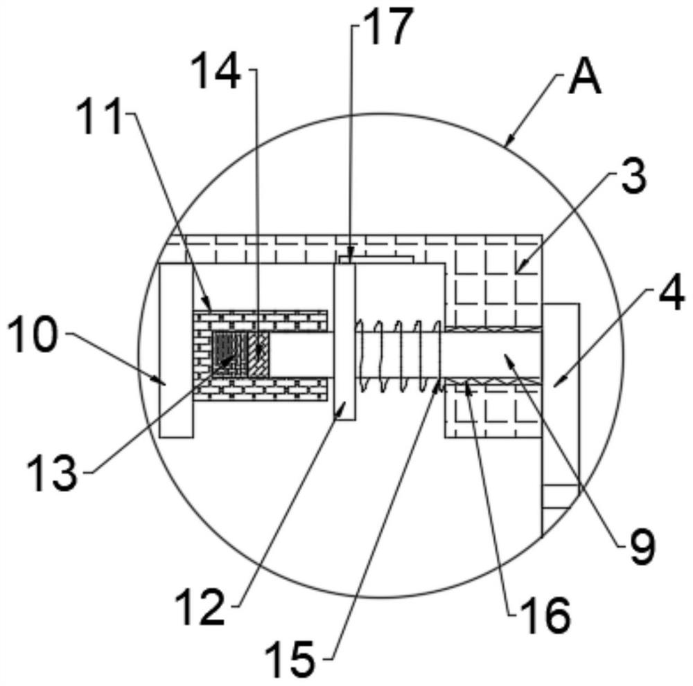
[0024] to combine Figure 1-5 , a special battery cooling device for new energy vehicles, including a mounting plate 1, a housing 3 and a battery pack 2, the housing 3 is fixed on the upper end of the mounting plate 1, the battery pack 2 is fixed inside the housing 3, the One side of the housing 3 is movably connected with a side plate 4, and the other side is provided with an air inlet slot 31, and the side plate 4 is provided with a heat dissipation hole 41, and the inside of the housing 3 is installed near the air inlet slot 31 A cooling fan 5, the air inlet groove 31 is connected with a filter screen 6, and the side plate 4 is fixed with a plurality of moving slide bars 9 near the side of the housing 3, and the moving slide bars 9 are connected to the side wall of the housing 3 Sliding connection, a plurality of first fixing plates 10 are fixed inside the housing 3 and close to the side plate 4, and sleeves 11 are connected to the plurality of first fixing plates 10, and t...

Embodiment 2

[0033] combine figure 1 , figure 2 and Figure 4 , a special battery cooling device for new energy vehicles. This embodiment further limits the present invention on the basis of Embodiment 1.

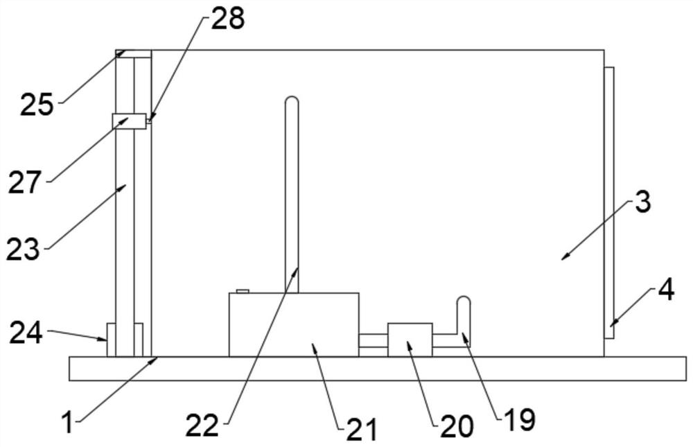
[0034] A second fixing plate 25 is connected to the side of the housing 3 and close to the filter screen 6, a threaded rod 26 and a limit rod 23 are arranged between the second fixing plate 25 and the mounting plate 1, and the threaded rod 26 and the Limiting rods 23 are respectively arranged on both sides of the filter screen 6, and one end of the threaded rod 26 is rotatably connected with the second fixed plate 25, and the other end is connected with the motor 24 transmission fixed on the upper end of the mounting plate 1. The limiting rods 23 The two ends are respectively fixedly connected with the second fixed plate 25 and the mounting plate 1, and the threaded rod 26 and the limit rod 23 are connected with a moving plate 27, and the moving plate 27 is threaded with the threaded...


PUM


Abstract

The invention relates to the technical field of battery heat dissipation, and particularly discloses a special battery heat dissipation device for a new energy automobile. The special battery heat dissipation device comprises a mounting plate, a shell and a battery pack, the shell is fixed at the upper end of the mounting plate, the battery pack is fixed in the shell, one side of the shell is movably connected with a side plate, and the other side of the shell is provided with an air inlet groove; heat dissipation holes are formed in the side plate, a heat dissipation fan is installed at the position, close to the air inlet groove, in the shell, a filter screen is connected into the air inlet groove, a plurality of movable sliding rods are fixed to the side, close to the shell, of the side plate, the movable sliding rods are in sliding connection with the side wall of the shell, and a plurality of first fixing plates are fixed to the positions, close to the side plates, in the shell. The heat loss in the shell can be greatly accelerated and the battery pack can be cooled in summer, and the heat loss in the shell can be greatly reduced and the battery pack can be insulated in winter, so that the working capability of the battery pack is improved.

Description

technical field [0001] The invention relates to the technical field of battery cooling, in particular to a special battery cooling device for new energy vehicles. Background technique [0002] New energy vehicle batteries can be divided into two categories, namely batteries and fuel cells. Batteries are suitable for pure new energy vehicles and can be classified as lead-acid batteries, nickel-based batteries (nickel-hydrogen and nickel-metal hydride batteries), sodium beta batteries (sodium-sulfur batteries and sodium-nickel chloride batteries), two Secondary lithium batteries, air batteries and other types. Fuel cells are dedicated to fuel cell new energy vehicles and can be divided into alkaline fuel cells (AFC), phosphoric acid fuel cells (PAFC), molten carbonate fuel cells (MCFC), solid oxide fuel cells (SOFC), proton exchange Membrane fuel cell (PEMFC), direct methanol fuel cell (DMFC) and other types. [0003] In new energy vehicles, the power battery pack is used a...

Claims


Application Information

Patent Timeline
Patent Type & Authority Applications(China)
IPC IPC(8): H01M10/613H01M10/615H01M10/625H01M10/635H01M10/6556H01M10/6563H01M10/6568H01M10/48H01M50/244H01M50/249
CPCH01M10/613H01M10/615H01M10/625H01M10/6556H01M10/635H01M10/486H01M10/6563H01M10/6568Y02E60/10
Inventor 孔庆光肖顺根阮群生
Owner NINGDE NORMAL UNIV
Why Eureka
Try Eureka