NTC-based battery temperature protection circuit

A technology for protecting the temperature of circuits and batteries, applied in emergency protection circuit devices, emergency protection devices with automatic disconnection, circuit devices, etc., can solve the problems of decreased stability of chemical substances, low detection sensitivity, and increased hidden dangers of batteries, etc., to achieve Effects of improved sensitivity, simple circuit structure design, high flexibility and practicality

Active Publication Date: 2021-10-19
深圳市万微半导体有限公司
View PDF4 Cites 2 Cited by
  • Summary
  • Abstract
  • Description
  • Claims
  • Application Information

AI Technical Summary

Problems solved by technology

In the low temperature state, the activity of the battery will drop sharply, and the capacity will drop sharply, and low temperature charging will have a greater impact on the chemical characteristics of the battery
In the high temperature state, the chemical activity of the battery is greatly increased, so the stability of the battery chemical substance drops sharply, and the safety of the battery is greatly reduced.
However, most of the existing batteries do not have temperature protection, which increases the hidden danger of using batteries.
[0003] In the prior art, there are also some technologies that can protect the charging and discharging of the battery, but in these applications, it is necessary to design a separate circuit to collect the temperature of the battery, and then form a feedback signal to control the working state of the battery, which leads to the charging and discharging of the battery. The structure of the temperature protection circuit is very complicated, and the detection sensitivity is also low, which is not conducive to the efficient utilization and sustainable development of energy, and is also not conducive to the integrated design of the circuit

Method used


Image

  • NTC-based battery temperature protection circuit
  • NTC-based battery temperature protection circuit
  • NTC-based battery temperature protection circuit

Examples


Embodiment 1

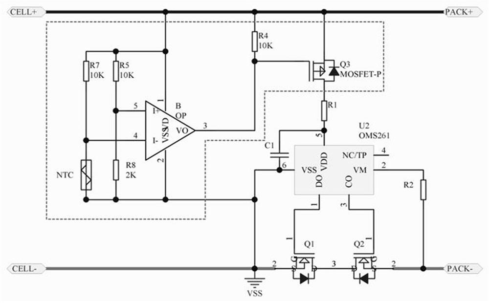
[0043] Embodiment 1: Circuit with charge and discharge high temperature protection

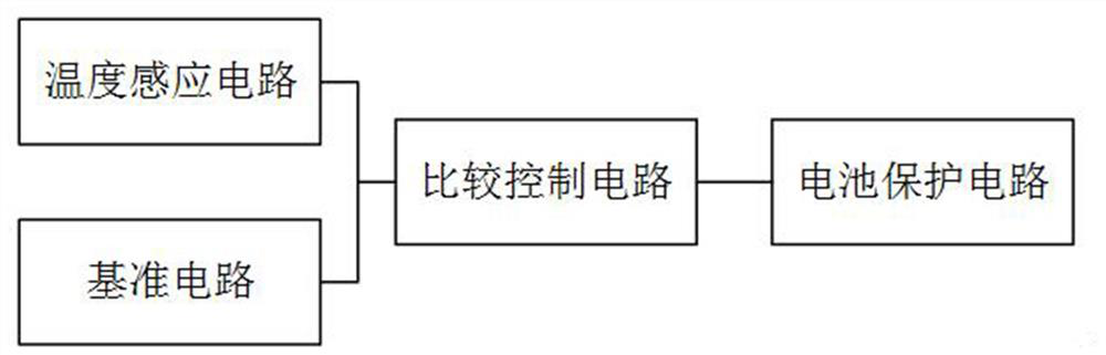
[0044] like figure 2 As shown, in this embodiment, the positive electrode CELL+ of the battery cell is respectively connected to the seventh resistor R7, the fifth resistor R5, the power supply terminal of the operational amplifier OP, the fourth resistor R4, and the source of the control MOS transistor (third MOS transistor Q3) and the positive pole of the battery PACK+, the other end of the seventh resistor R7 is respectively connected to the inverting input terminal of the operational amplifier OP and the NTC thermistor, and the other end of the fifth resistor R5 is respectively connected to the non-inverting input terminal of the operational amplifier OP and the reference resistor (that is, the first Eight resistors R8), the output terminal of the operational amplifier is respectively connected to the other end of the fourth resistor R4 and the gate of the third MOS transistor Q3, and the...

Embodiment 2

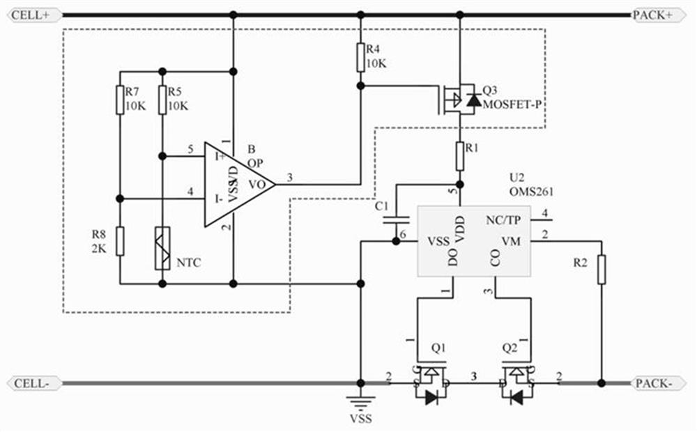
[0050] Embodiment 2: Circuit with charge and discharge low temperature protection

[0051] like image 3 As shown, the difference from Embodiment 1 is that this embodiment exchanges the positions of the eighth resistor R8 and the NTC thermistor on the basis of Embodiment 1, that is, the NTC thermistor’s voltage divider is input to the non-inverting input of the operational amplifier OP Terminal, the divided voltage of the eighth resistor R8 is input to the inverting input terminal of the operational amplifier OP.

[0052] At normal temperature, the resistance of the NTC thermistor is higher (lower than the resistance of the eighth resistor R8), and the divided voltage of the branch where it is located is smaller than the divided voltage of the eighth resistor R8 in the branch where it is located, VI+ If it is less than VI-, the operational amplifier OP outputs a low voltage, the third MOS transistor Q3 is turned on, and the battery protection chip U2 works normally. At this t...

Embodiment 3

[0056] Embodiment 3: Circuit with charging high temperature protection

[0057] like Figure 4 As shown, the difference from Embodiment 1 is that in this embodiment, the power supply terminal of the battery protection chip U2 is directly connected to the battery positive electrode PACK+ through the first resistor R1, and the charging output terminal CO of the battery protection chip U2 is connected to the control MOS tube (third The source of the MOS transistor Q3), the gate of the third MOS transistor Q3 is connected to the output terminal of the operational amplifier OP, its drain is connected to the battery negative pole PACK- through the third resistor R3, and the drain of the third MOS transistor Q3 It is also connected to the gate of the charging switch tube (that is, the second MOS transistor Q2).

[0058] Under normal temperature, the resistance value of NTC thermistor is relatively high, and the divided voltage of the NTC thermistor in its branch is greater than the ...


PUM


Abstract

The invention discloses an NTC (Negative Temperature Coefficient)-based battery temperature protection circuit in the field of integrated circuit design. The battery temperature protection circuit comprises a battery protection circuit, the input end of the battery protection circuit is connected with a comparison control circuit, two input ends of the comparison control circuit are respectively connected with a temperature sensing circuit and a reference circuit, and an NTC thermistor is arranged in the temperature sensing circuit. Temperature detection is achieved through the NTC thermistor, over-temperature control is achieved through an operational amplifier and a control MOS tube, then temperature protection of the battery is achieved, the whole circuit structure is simple in design, and the design requirements of an existing highly-integrated and miniaturized integrated circuit are met; in addition, the sensitivity adjustment requirement of the system circuit can be met by adjusting the resistance value ratio of a reference resistor and the NTC thermistor in a branch circuit according to the requirement, the sensitivity of the whole battery temperature protection circuit is greatly improved, and the battery temperature protection circuit has high flexibility and practicability.

Description

technical field [0001] The invention relates to the field of integrated circuit design, in particular to an NTC-based battery temperature protection circuit. Background technique [0002] With the development of science and technology, the application of emerging batteries such as lithium-ion batteries is gradually increasing. The battery is very sensitive to temperature. The material and performance of the lithium battery itself determine that it cannot be charged and discharged at ultra-high temperature and ultra-low temperature. In the low temperature state, the activity of the battery will decrease sharply, and the capacity will drop sharply, and low temperature charging will have a great impact on the chemical characteristics of the battery. In the high temperature state, the chemical activity of the battery increases greatly, so the stability of the battery chemical substance drops sharply, and the safety guarantee of the battery is greatly reduced. However, most exi...

Claims


Application Information

Patent Timeline
IPC IPC(8): H02H7/18H02H5/04
CPCH02H7/18H02H5/042
Inventor 朱志勇刘磊熊力嘉
Owner 深圳市万微半导体有限公司
Why Eureka
Try Eureka