High-frequency reciprocating reversing workbench and method for machining punch through high-frequency reciprocating reversing workbench

A technology of workbench and workbench, which is applied in the direction of metal processing equipment, manufacturing tools, grinding workpiece supports, etc., can solve the problems of low processing efficiency, achieve high processing efficiency, improve processing efficiency, and have strong practicability

Active Publication Date: 2021-10-22
陕西诺贝特自动化科技股份有限公司
View PDF9 Cites 0 Cited by
  • Summary
  • Abstract
  • Description
  • Claims
  • Application Information

AI Technical Summary

Problems solved by technology

[0004] In order to solve the technical problem of low processing efficiency of punch parts, the present invention provides a high-frequency reciprocating reversing worktable and a method for processing punches using it. The parts tray is fixed on the magnetic table by magnetic force, making the fixing of parts more convenient. ;One row or two rows of parts on the parts tray are processed simultaneously on the high-frequency reciprocating workbench, which improves the processing efficiency; at the same time, multiple parts trays can be prepared. When one parts tray is placed on the workbench for processing, Other parts trays can be loaded with parts at the same time. After the parts on the workbench are processed, the magnetic table is demagnetized, the parts tray is replaced, and the magnetic table is magnetized again, so that the next batch of parts can be processed conveniently, thereby further improving Processing efficiency

Method used


Image

  • High-frequency reciprocating reversing workbench and method for machining punch through high-frequency reciprocating reversing workbench
  • High-frequency reciprocating reversing workbench and method for machining punch through high-frequency reciprocating reversing workbench
  • High-frequency reciprocating reversing workbench and method for machining punch through high-frequency reciprocating reversing workbench

Examples


Embodiment 1

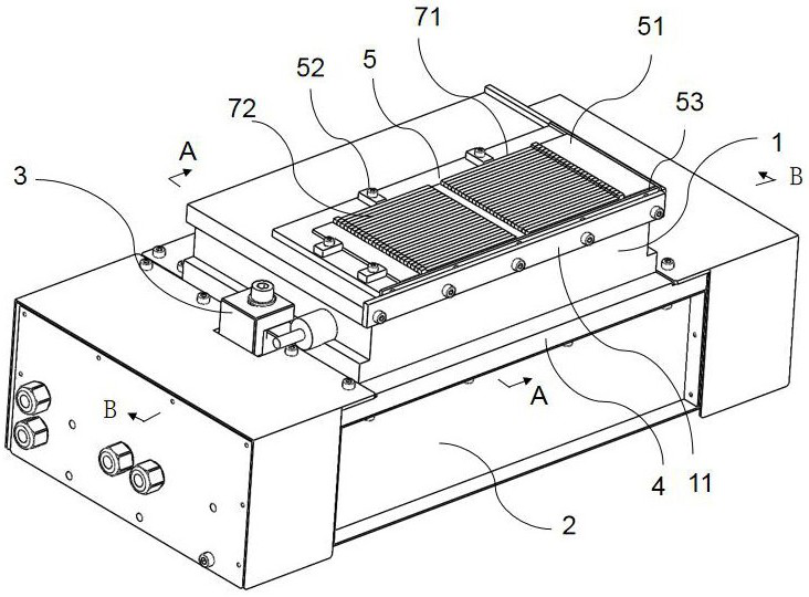
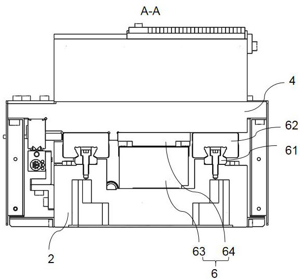
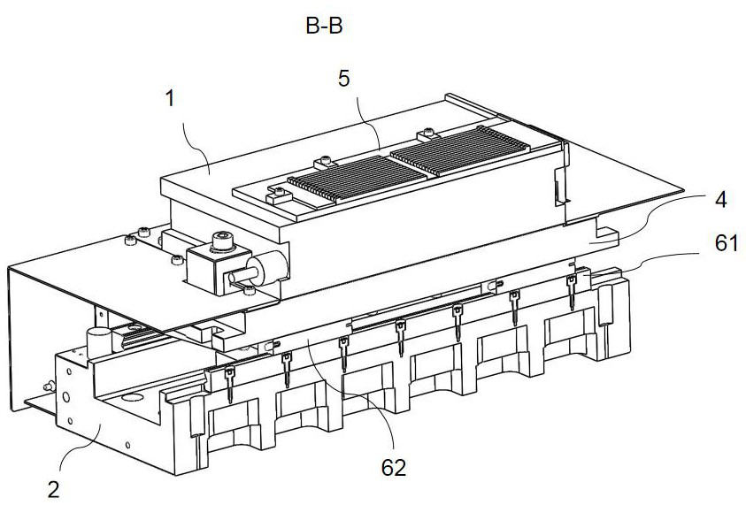
[0059] This embodiment provides a high-frequency reciprocating commutation workbench, such as Figure 1-3 As shown, it includes a magnetic table 1, a magnetic table installation base 2, a parts tray 5 and a reciprocating drive mechanism 6;

[0060] Wherein, the magnetic table 1 is fixedly connected to the slider 62, the magnetic table installation base 2 is fixedly connected to the linear guide rail 61, and the slider 62 is slidably connected to the linear guide rail 61;

[0061] The reciprocating drive mechanism 6 drives the slide block 62 to slide on the linear guide rail 61;

[0062] The parts tray 5 can be fixed on the upper surface of the magnetic table 1 by magnetic force. Those skilled in the art know that the magnetic table 1 is a device that can generate magnetic force when it is energized, and the parts tray 5 can be fixed on the magnetic table 1 by magnetic force. surface, the parts tray 5 needs to be made of a material that can be attracted by the magnetic force o...

Embodiment 2

[0077] The present invention also provides a punch processing method, the steps of which are as follows: Figure 4-5 shown, including:

[0078] S10. Arranging a plurality of parts in a row on the parts tray 5 to form a first part row 71;

[0079] Now, the non-processed end of the part abuts against the parts tray baffle 53, and the parts are placed in sequence. Of course, a parts baffle 51 can be placed against the parts tray baffle 53 first, and then the parts are placed, so that Its unprocessed end abuts on the parts baffle 51; In the two opposite directions of the baffle plate 53, a connector is used to fix the fixed block on the parts tray 5, thereby completing the placing of the parts on the parts tray;

[0080] S20. Place the parts tray 5 on the magnetic table 1 of the high-frequency reciprocating reversing workbench as in Embodiment 1, magnetize the magnetic table 1, and fix the parts tray 5 and the magnetic table 1 by magnetic force;

[0081] Among them, the connect...

Embodiment 3

[0094] The difference between the third embodiment and the second embodiment is that the second embodiment processes one row of parts at a time, while the third embodiment processes two rows of parts at a time, such as Figure 7 shown.

[0095]Specifically, in step S10, two rows of parts are placed, respectively the first part row 71 and the second part row 72, such as figure 1 As shown, a part baffle 53 is arranged between the first part row 71 and the second part row 72; the first part row 71 and the second part row 72 are symmetrically arranged, and the ends to be processed are oppositely arranged.

[0096] Thus, during processing, such as Figure 7 As shown, the grinding wheel rotates at a fixed position, only the up and down feed is adjusted, and the parts follow the high-frequency reciprocating reversing table to reciprocate in the horizontal direction and perpendicular to the axis of the grinding wheel, thereby completing the processing of the parts by the grinding whe...


PUM


Abstract

The invention is suitable for the technical field of machine tools, and provides a high-frequency reciprocating reversing workbench and a method for machining a punch through the high-frequency reciprocating reversing workbench. The high-frequency reciprocating reversing workbench comprises a magnetic table, a magnetic table mounting base, a part tray and a reciprocating motion driving mechanism, wherein the magnetic table is fixedly connected with a sliding block, the magnetic table mounting base is fixedly connected with a linear guide rail, and the sliding block is slidably connected with the linear guide rail; the reciprocating motion driving mechanism drives the sliding block to slide on the linear guide rail; the part tray is fixed on the upper surface of the magnetic table through magnetic force, so that it is more convenient to fix the part; and one row or two rows of parts on the part tray are processed at the same time, so that the processing efficiency is improved. Meanwhile, a plurality of part trays can be prepared. When one part tray is placed on the workbench for machining, other part trays can load the parts at the same time; after the parts on the workbench are machined, the magnetic table is demagnetized, the part trays are replaced, and the magnetic table is magnetized, so that the next batch of parts can be machined conveniently, and the machining efficiency is further improved.

Description

technical field [0001] The invention belongs to the technical field of machine tools, and in particular relates to a high-frequency reciprocating and reversing workbench and a method for processing punches using it. Background technique [0002] When the lead frame is produced, holes need to be punched on it, which requires many punches. And because the diameter of the hole is usually all small, so the punch is easily broken, resulting in the need to frequently replace the punch, and the usage of the punch is relatively large. At present, when processing punches, a punch is usually fixed with a vise clamp, and then a grinding wheel is used to process the punch. It can only process one punch at a time, the processing efficiency is low, and the precision is poor. [0003] Patent CN201210328060.7 discloses a lead frame punch processing device. When in use, the punch materials to be processed are discharged one by one on the surface of the base. After the fixation is completed...

Claims


Application Information

Patent Timeline
Patent Type & Authority Applications(China)
IPC IPC(8): B24B19/00B24B41/06B24B41/02B24B47/04
CPCB24B19/00B24B41/06B24B41/02B24B47/04
Inventor 吴小鑫王建鹏袁朗王成兵郭军靳炜张双琳
Owner 陕西诺贝特自动化科技股份有限公司
Why Eureka
Try Eureka