Electric automation material automatic placing and positioning device

An electrical automation and positioning device technology, applied in the direction of transportation and packaging, conveyor objects, etc., can solve the problems of inability to adjust the position of materials, complicated operation of electrical automation equipment, etc., to improve service life, reduce use difficulty, and reduce wear speed Effect

Pending Publication Date: 2021-10-22
黄序浩
View PDF8 Cites 0 Cited by
  • Summary
  • Abstract
  • Description
  • Claims
  • Application Information

AI Technical Summary

Problems solved by technology

[0005] Aiming at the deficiencies of the prior art, the present invention provides an automatic placement and positioning device for electrical automation materials, which solves the problem that the existing electrical automation equipment is complicated to operate and cannot conveniently adjust the position of materials with an inclined angle on the conveyor belt, and improves The service life of the device is extended, and the secondary pollution caused by the material leakage on the equipment to the subsequent materials can be prevented

Method used


Image

  • Electric automation material automatic placing and positioning device
  • Electric automation material automatic placing and positioning device
  • Electric automation material automatic placing and positioning device

Examples


Embodiment 1

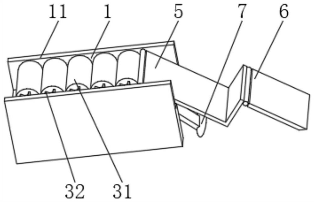
[0034] see Figure 1-3 , the present invention provides a technical solution: a device for automatically placing and positioning electrical automation materials, including

[0035] An installation frame 1, the installation frame 1 has an outer frame 11, and openings at both ends of the outer frame 11;

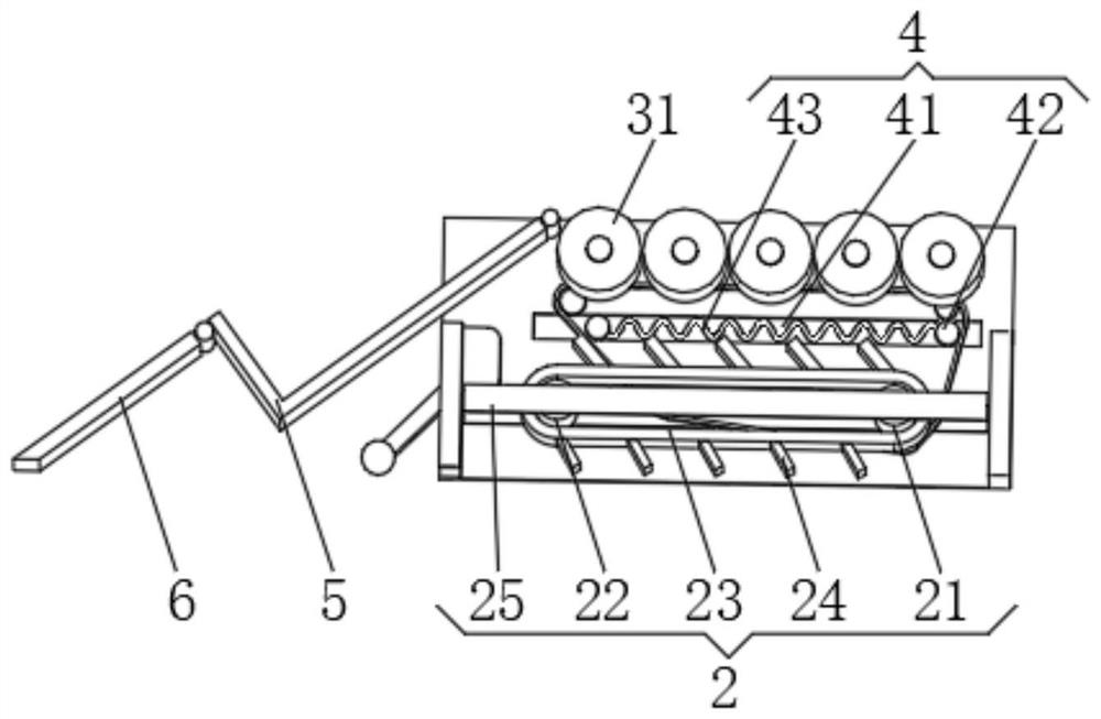
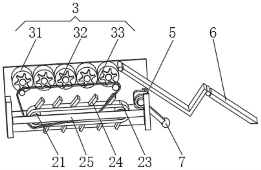
[0036] Driving device 2, this driving device 2 has driving wheel 21, driven wheel 22, transmission belt 23 and anti-slip tooth 24, anti-slip tooth 24 is arranged on the outside of transmission belt 23, and anti-slip tooth 24 extends away from the end of transmission belt 23 to the outer frame 11 outside;

[0037] Positioning device 3, this positioning device 3 has positioning roller 31, and one end of positioning roller 31 is provided with driven gear 32, and positioning device 3 also has driving chain 33, and the inner wall side of outer frame 11 is provided with guide wheel, and driving chain 33 and The driving wheel 21 is connected.

[0038]When in use, the outer frame 11...

Embodiment 2

[0044] see Figure 1-6 , the present invention provides a technical solution: on the basis of Embodiment 1, an anti-leakage cavity is provided on the outside of the positioning roller 31, and an isolation plate 81 is evenly installed inside the anti-leakage cavity, and a spacer is provided between the two sides of the isolation plate 81. Release paper 82, release paper 82 is absorbent paper.

[0045] One end of the isolation plate 81 is provided with an arc-shaped bump 83, and both sides of the arc-shaped bump 83 are provided with an extension cloth 84, and one end of the extension cloth 84 is provided with a sticky block 85, and the extension cloth 84 is close to one end of the arc-shaped bump 83 Scissors 86 are provided.

[0046] An adsorption plate 91 is arranged between the two sides of the isolation plate 81 , and a magnet block 92 is evenly arranged on the outside of the adsorption plate 91 .

[0047] During use, the barrel-shaped material on the electrical automation ...


PUM


Abstract

The invention discloses an electric automation material automatic placing and positioning device. The device comprises a mounting frame, a driving device and a positioning device, wherein the mounting frame is provided with an outer frame and inlet and outlet openings formed in two ends of the outer frame; the driving device is provided with a driving wheel, a driven wheel, a transmission belt and anti-skid teeth, the anti-skid teeth are arranged outside the transmission belt, and the ends, away from the transmission belt, of the anti-skid teeth extend to the outside of the outer frame; and the positioning device is provided with a positioning roller, a driven gear is arranged at one end of the positioning roller, and the positioning device is further provided with a driving chain. The invention relates to the technical field of electric automation. According to the electric automation material placing and positioning device, the purpose of reducing the use difficulty of the device is achieved, materials with inclined angles on a conveying belt can be conveniently aligned, then the service life of the device is prolonged, and secondary pollution caused by material leakage on the device to follow-up materials can be prevented.

Description

technical field [0001] The invention relates to the technical field of electric automation, in particular to a device for automatically placing and positioning electric automation materials. Background technique [0002] The full name of electrical automation is electrical engineering and automation, which involves power electronics technology, computer technology, electrical and electrical technology information and network control technology, mechatronics technology and many other fields. Electrical integration, mechanical and electrical integration, software and hardware integration, electrical technology and electronic technology, components and systems, so that students can acquire knowledge in the fields of electrical and electronics, system control, electrical control, power system automation, electrical automation devices, and computer application technology. basic skills. [0003] However, the existing electrical automation equipment is complicated to operate, and ...

Claims


Application Information

Patent Timeline
IPC IPC(8): B65G47/82B65G47/04B65G47/22
CPCB65G47/82B65G47/04B65G47/22
Inventor 黄序浩
Owner 黄序浩
Why Eureka
Try Eureka