
Injector capillary liquid flow and air tightness testing device

A technology of air tightness testing and capillary tubes, which is applied in the direction of measuring devices, testing of machines/structural components, liquid tightness measurement using liquid/vacuum degree, etc. Solve problems such as cumbersome testing process, avoid duplication of manual labor, flexible testing mode, and improve testing efficiency

Active Publication Date: 2021-10-22
湖北三江航天红林探控有限公司
View PDF8 Cites 2 Cited by
  • Summary
  • Abstract
  • Description
  • Claims
  • Application Information

AI Technical Summary

Problems solved by technology

[0003] The existing injector capillary liquid flow and airtight test devices are basically divided into two categories. One type of test device tests the whole injector after the capillary is brazed. This test device has a simple structure, but can only get The overall flow characteristics of the injector, and then calculate the average flow characteristics of a single capillary, the measurement accuracy is low, if the flow characteristics or air tightness of a certain capillary is unqualified, the entire injector will be scrapped, and the product qualification rate is difficult. Effective lifting; another type of test device reserves a certain length of straight line after the single capillary is bent, and welds the pipe joints at both ends for testing. After the test is completed, the pipe joints are cut off, the end of the capillary is polished, and the orifice is trimmed , Brazing is an injector, the testing process is cumbersome, the testing process is time-consuming and laborious, and it is easy to cause capillary deformation and cannot be assembled

Method used


Image

  • Injector capillary liquid flow and air tightness testing device
  • Injector capillary liquid flow and air tightness testing device
  • Injector capillary liquid flow and air tightness testing device

Examples


Embodiment Construction

[0037] The technical solutions of the present invention will be clearly and completely described below in conjunction with the accompanying drawings of the present invention. Based on the embodiments of the present invention, all other embodiments obtained by persons of ordinary skill in the art without creative efforts fall within the protection scope of the present invention.

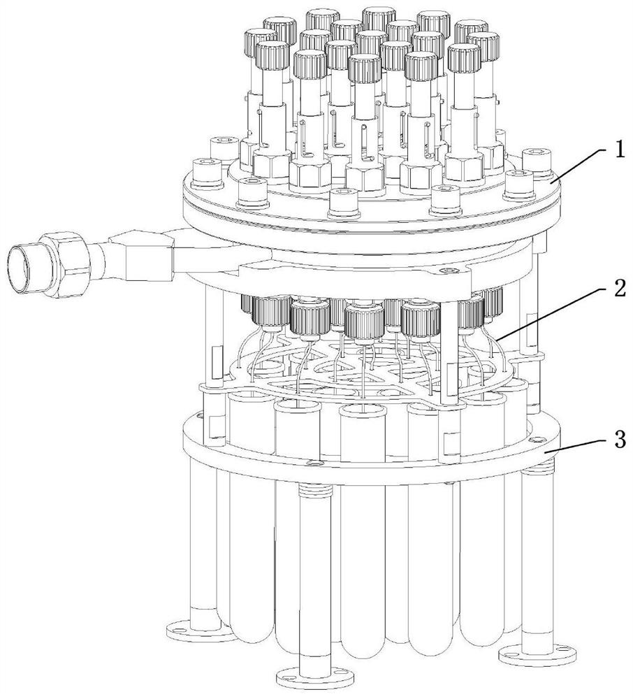
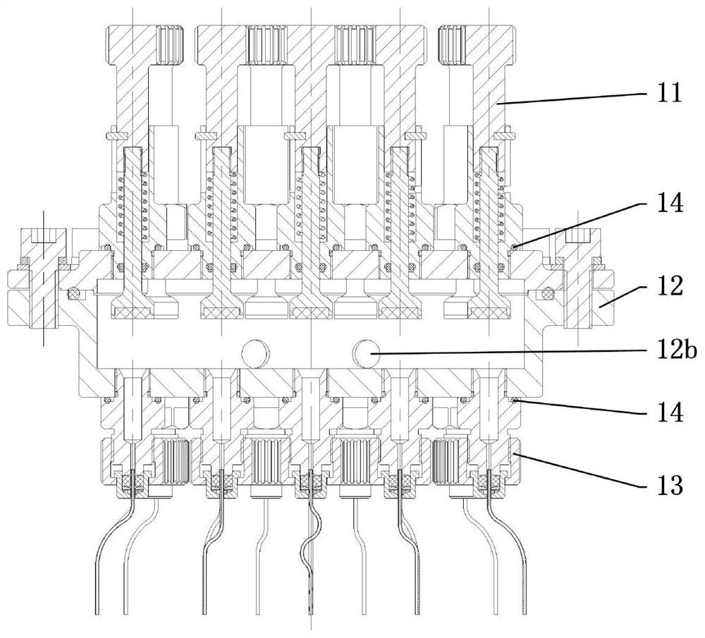
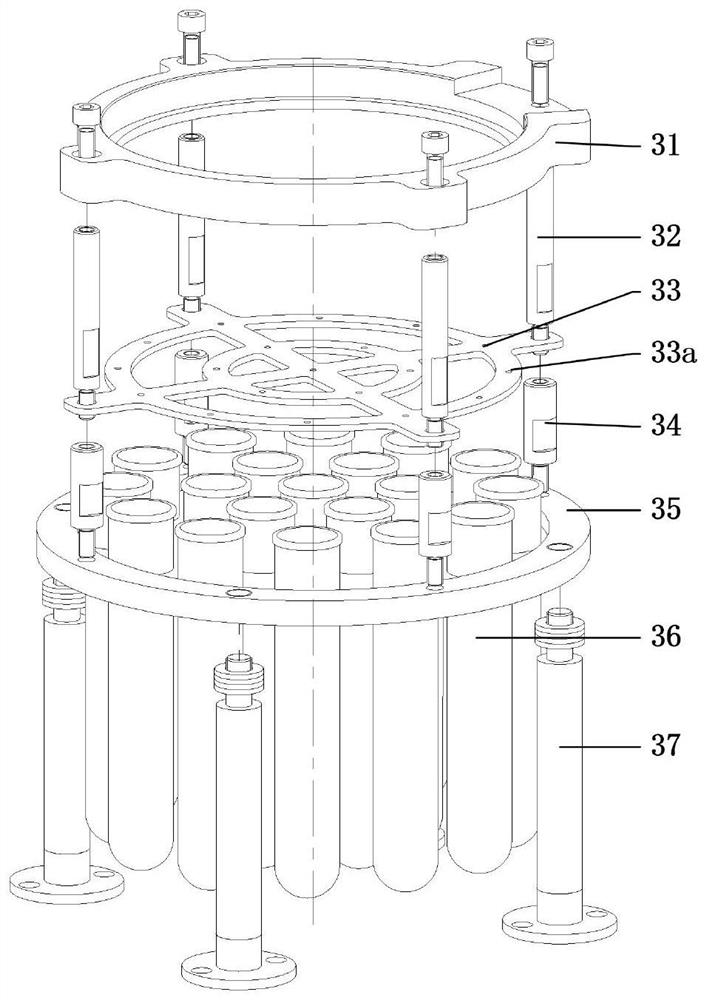
[0038] Such as figure 1 As shown, the present embodiment provides a capillary liquid flow and airtight test device of an injector, comprising: a test assembly 1, a capillary 2, a collection assembly 3 and an airtight assembly 4; the installation of the test assembly 1 on the top of the collection assembly 3 In the hole, it is connected with the test equipment through the guide tube 124; the capillary 2 of the injector includes multiple types, is clamped in the test assembly 1 respectively, and is aligned with the collection assembly 3; when the test starts, the liquid flow test equipment The valve of...


PUM


Abstract

The invention discloses an injector capillary liquid flow and air tightness testing device which comprises a testing assembly, a capillary, a collecting assembly and an air tightness assembly. The testing assembly is installed on the upper portion of the collecting assembly, the capillary is clamped in the testing assembly and aligned with the collecting assembly, and the airtight assembly is selectively installed at an outlet of the capillary. A test medium is sprayed out by the capillary after entering the testing assembly and is directly sprayed into the collecting assembly to complete a liquid flow test, the airtight assembly is installed at an outlet of the capillary according to test requirements, and the test medium is injected into the testing assembly to complete an airtight test. Through the independent sealing effect of a sealing part, the capillary at any position can be tested independently, and the capillary can also be tested integrally. The technical scheme of the invention has the characteristics of simple, convenient and efficient test process, simple structure and low cost, can reject unqualified products before the capillary is brazed into the injector, and has significant significance for improving the product percent of pass and reducing economic waste.

Description

technical field [0001] The invention relates to the field of single-component liquid rocket engine testing, in particular to an injector capillary liquid flow and airtight testing device. Background technique [0002] The injector is an important component of the monolithic liquid rocket engine, and its performance determines many key technical indicators such as the working life, starting performance, working efficiency and stability of the engine. As the injection tube of the injector, the capillary controls the flow rate and injection uniformity of the propellant, which puts forward high requirements for its inner diameter accuracy, surface roughness, end face geometry and flow consistency. The inner diameter of the capillary used in the vast majority of monocomponent liquid rocket engine injectors is less than 1mm, and the wall thickness is about 0.15mm. Assemble multiple capillaries in the upper and lower injection trays to complete the multi-pass brazing process. The...

Claims


Application Information

Patent Timeline
Patent Type & Authority Applications(China)
IPC IPC(8): G01M3/02G01M10/00B07C5/34
CPCG01M3/02G01M10/00B07C5/34B07C5/3404
Inventor 曾雪宁郝雪杰张迎港
Owner 湖北三江航天红林探控有限公司
Learn More