Production Control in a Blow Room

a production control and blow room technology, applied in the direction of computer control, program control, instruments, etc., can solve the problems of operating the supplying machine in a range, and achieve the effect of high-quality products

Active Publication Date: 2018-12-13
MASCHINENFABRIK RIETER AG
View PDF14 Cites 3 Cited by
  • Summary
  • Abstract
  • Description
  • Claims
  • Application Information

AI Technical Summary

Benefits of technology

[0019]The production area is determined by additional fiber processing machines located between the supplying machine and the machine to be supplied. These machines, which do not have any direct influence on the production level but instead are passively tied into the fiber transport path from the supplying machine to the machine to be supplied, oper

Problems solved by technology

This avoids operating the supplying machine i

Method used


Image

  • Production Control in a Blow Room

Examples


Embodiment Construction

[0023]Reference will now be made to embodiments of the invention, one or more examples of which are shown in the drawings. Each embodiment is provided by way of explanation of the invention, and not as a limitation of the invention. For example features illustrated or described as part of one embodiment can be combined with another embodiment to yield still another embodiment. It is intended that the present invention include these and other modifications and variations to the embodiments described herein.

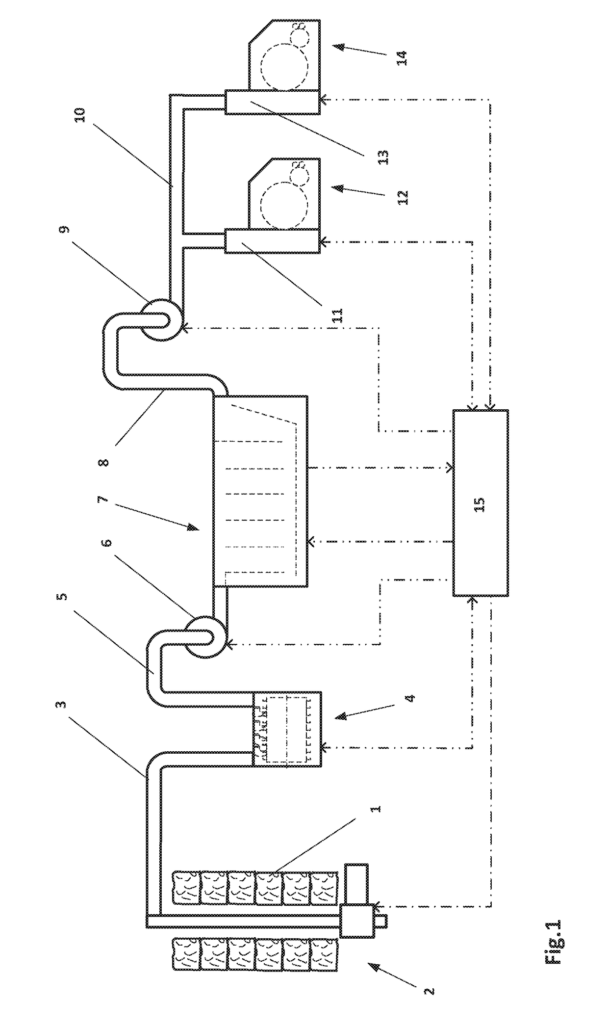
[0024]FIG. 1 shows a schematic diagram of an example of an arrangement of machines in a blow room. This diagram shows simplified equipment for a blow room, which in many cases consists of additional machines in a wide variety of arrangements.

[0025]At the start, there is a bale opener 2, which takes fiber flocks from fiber bales 1 that have already been made ready and sends them to a transport line 3. The fiber flocks are then sent through the transport line 3 to a cleaner 4. After ...


PUM

PropertyMeasurementUnit
Areaaaaaaaaaaa
Levelaaaaaaaaaa

Abstract

A system and corresponding method are provided for controlling production in a blow room, the blow room including a controller, a supplying machine having a supplying part, and a machine to be supplied that has a filling level measurement. The supplying machine and the machine to be supplied are connected to the controller. A production area is defined for the supplying machine and includes a minimum production and a maximum production. Production of the supplying part of the supplying machine is determined based on a filling level of the filling level measurement. When production of the production area drops below the minimum production, the supplying part of the supplying machine is shut down, the shutdown taking place independently of the filling level of the machine to be supplied.

Description

FIELD OF THE INVENTION[0001]The invention relates to a method and a device for controlling production in a blow room.BACKGROUND[0002]Fiber processing machines, such as cleaners, temporary storage devices, mixers or cards are used in the blow room for cleaning, mixing and separation of the fiber material into individual fibers as well as parallelization of the fibers.[0003]In a blow room, the fibers to be processed for the spinning mill pass through a plurality of processing stages. In the first stage, the fibers are separated in the form of fiber flocks from fiber bales. So-called bale openers are mostly used for this purpose. These fiber flocks are removed from the bale opener by means of a pneumatic conveyor device and sent to a downstream cleaning machine. The pneumatic conveyor device consists essentially of a pipeline and a fan to create the required stream of conveyor air. The cleaned fiber flocks are in turn sent pneumatically from the cleaning machine to a mixer. The fiber f...

Claims


Application Information

Patent Timeline
IPC IPC(8): D01G23/04D01G23/08D01G21/00D01G31/00G05B19/4155
CPCD01G23/04D01G23/08D01G21/00D01G31/006G05B19/4155D01G15/02D01G7/00D01G9/00D01G13/00G05B2219/45238D01G15/40D01G23/06D01G9/14
Inventor LUTHARD, RETOGSCHLIESSER, GERHARD
Owner MASCHINENFABRIK RIETER AG
Why Eureka
Try Eureka