Aliasing signal modulation type identification method based on time-frequency analysis and constellation diagram analysis

An aliasing signal, time-frequency analysis technology, applied in signal pattern recognition, character and pattern recognition, image analysis and other directions, can solve the problems of limited recognition accuracy, slow speed, and difficulty in adapting to complex and changeable electromagnetic environments. , to achieve the effect of strong practical value and small computing power requirements

Pending Publication Date: 2021-10-22
SOUTHEAST UNIV
View PDF0 Cites 0 Cited by
  • Summary
  • Abstract
  • Description
  • Claims
  • Application Information

AI Technical Summary

Problems solved by technology

[0008] To sum up, the existing signal recognition and sorting technology widely uses neural networks, and the introduction of neural networks puts forward extremely high requirements on the hardware modules of signal processing, which consumes huge computing power and is slow.
Secondly, the recognition accuracy that the above-mentioned technologies can achieve in the electromagnetic environment where multiple modulation signals are mixed is very limited, and it is difficult to adapt to the complex and changeable electromagnetic environment.

Method used


Image

  • Aliasing signal modulation type identification method based on time-frequency analysis and constellation diagram analysis
  • Aliasing signal modulation type identification method based on time-frequency analysis and constellation diagram analysis
  • Aliasing signal modulation type identification method based on time-frequency analysis and constellation diagram analysis

Examples


Embodiment 1

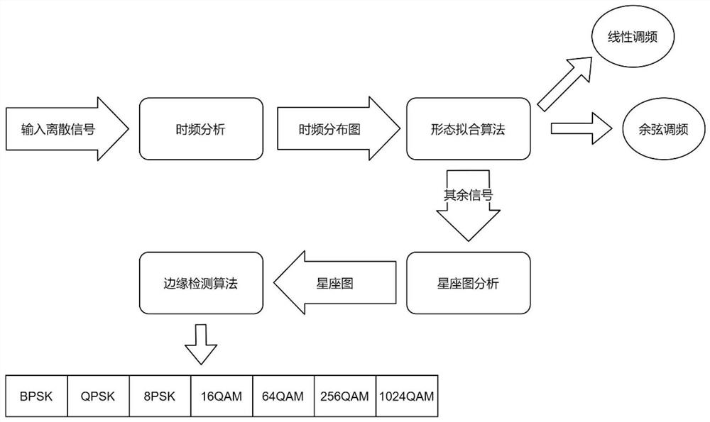
[0120] Embodiment 1: see Figure 1-Figure 9 , a method for identifying modulation types of aliased signals based on time-frequency analysis and constellation diagram analysis, said method comprising the following steps:

[0121] Step 1: Identify the type of analog modulation in the aliased signal using time-frequency analysis combined with shape fitting;

[0122] Step 2: Identify the type of digital modulation in the aliased signal using constellation analysis combined with edge detection.

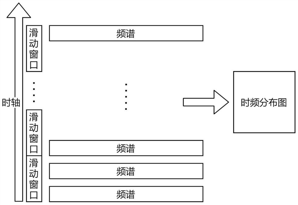
[0123] like figure 1 As shown, using the time-frequency analysis method (including short-time Fourier transform, Morlet wavelet transform, etc.), draw the time-frequency distribution diagram, and use the shape fitting algorithm to identify the analog modulation signal in the time-frequency distribution diagram. For the digital modulation type in the aliased signal, use the constellation diagram analysis method to draw the signal constellation diagram, and use the edge detection algorithm...

Embodiment approach

[0217] The input signal is composed of one of digital modulation methods such as linear frequency modulation LFM, sinusoidal frequency modulation SFM and BPSK, QPSK, 8PSK, 16QAM, etc. In the case of a signal-to-noise ratio of 25dB, the short-time Fourier transform (DFT) is used to draw the time-frequency distribution diagram of the input signal, as shown in Image 6 Shown:

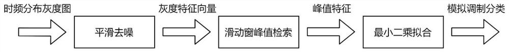
[0218] It is easy to see that the signal is divided into three parts in the time-frequency domain, and the three parts can be distinguished by the shape fitting method, the two analog modulation types are separated, and the analog modulation type and the digital modulation type are separated .

[0219] Firstly, smooth and denoise the signal, take 5 pixels in the vertical direction as a unit, cut the time-frequency image into several horizontal bars, and superimpose the five vertical pixel values ​​into a one-dimensional gray value vector. The processed image is as Figure 7 shown.

[0220] Using a tria...


PUM


Abstract

The invention discloses an aliasing signal modulation type identification method based on time-frequency analysis and constellation diagram analysis. According to the method, each different modulation type can be automatically identified from aliasing signals in nine different modulation modes including digital and analog modulation modes. The method is based on parameter fitting and small-range variance. The method has the advantages of low overhead, high speed and high recognition accuracy, is applied to recognition and sorting of baseband aliasing signals in the field of wireless communication/radar/electronic countermeasure, and can realize low-overhead quick cognition of the current electromagnetic environment.

Description

[0001] Technical field [0002] The invention relates to an aliasing signal modulation type identification method based on time-frequency analysis and constellation diagram analysis, and belongs to the field of baseband signal processing in wireless communication / radar / electronic countermeasures. Background technique [0003] With the continuous progress in the field of electronic countermeasures in modern military warfare, the density of electromagnetic signals in electronic countermeasures is increasing day by day, and various new radars are continuously put into use and gradually occupy a dominant position, so the modulation method adopted by the radar emitter signal will change. More and more complex, such as frequency modulation, phase modulation, amplitude modulation, etc. The classification and identification process of radar emitter signals plays an irreplaceable role in the field of electronic countermeasures. With the more flexible and changeable radar emitter signal...

Claims


Application Information

Patent Timeline
Patent Type & Authority Applications(China)
IPC IPC(8): G06K9/00G06K9/62G06N3/02G06T5/20G06T5/30G06T7/13
CPCG06N3/02G06T5/30G06T5/20G06T7/13G06F2218/02G06F2218/12G06F18/214
Inventor 李晟屹陈文迪张帆
Owner SOUTHEAST UNIV
Why Eureka
Try Eureka