
Method for forming semiconductor device

A semiconductor and device technology, applied in the field of semiconductor device formation, can solve problems such as semiconductor device performance needs to be improved

Pending Publication Date: 2021-10-22
SEMICON MFG INT (SHANGHAI) CORP +1
View PDF0 Cites 0 Cited by
  • Summary
  • Abstract
  • Description
  • Claims
  • Application Information

AI Technical Summary

Problems solved by technology

[0004] However, the performance of existing semiconductor devices still needs to be improved

Method used


Image

  • Method for forming semiconductor device
  • Method for forming semiconductor device
  • Method for forming semiconductor device

Examples


Embodiment Construction

[0039] As mentioned in the background art, existing semiconductor structures have the problem of poor performance.

[0040] A method of forming a semiconductor device, comprising:

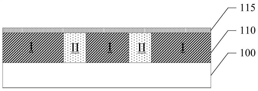
[0041] see figure 1 , providing a substrate (not shown), on which a layer to be etched 100 and a spacer material layer 110 located on the layer to be etched 100 are formed; a spacer doped region I is formed in part of the spacer material layer 110 , the spacer material layer 110 at the side of the spacer doped region I is the spacer of the non-doped region II.

[0042] The process of forming the spacer doped region I includes: a patterned mask layer on the spacer material layer 110, the patterned mask layer has a mask opening; the spacer material layer at the bottom of the mask opening 110 Perform ion implantation to form the interval doped region I; after that, remove the patterned mask layer.

[0043] An ashing process is used in the process of removing the patterned mask layer, and the ashin...


PUM

PropertyMeasurementUnit
thicknessaaaaaaaaaa
heightaaaaaaaaaa

Abstract

The invention discloses a method for forming a semiconductor device, and the method comprises the following steps: removing a first oxide layer by adopting a first wet etching process, performing oxidation treatment on the top surface of an interval non-doped region II, and forming a second oxide layer on the top of the interval non-doped region II; performing etching to remove the second oxide layer at the top of the interval non-doped region by a second wet etching process, so after the second oxide layer is removed, the defects at the top of the interval non-doped region are relatively few, and residual side wall materials are prevented from being formed in the cavity in the process of forming the side wall mask layer; therefore, the blocking of the residual side wall material in the cavity when the interval non-doped region is removed is avoided, the interval non-doped region is easy to remove, and the performance of the formed semiconductor device can be improved.

Description

technical field [0001] The invention relates to the technical field of semiconductors, in particular to a method for forming a semiconductor device. Background technique [0002] With the improvement of the integration level of semiconductor devices, the application of transistors is more and more extensive, which also puts forward higher requirements on the performance of transistors. [0003] The traditional planar field-effect transistor has weak control ability to the channel current, and a new complementary metal-oxide-semiconductor transistor—Fin Field-Effect Transistor (FinFET) is produced accordingly. The fin field effect transistor is a new type of multi-gate device, which generally includes a fin protruding from the surface of the substrate, a gate crossing the fin, and source-drain doped regions in the fins on both sides of the gate. [0004] However, the performance of existing semiconductor devices still needs to be improved. Contents of the invention [000...

Claims


Application Information

Patent Timeline
Patent Type & Authority Applications(China)
IPC IPC(8): H01L21/8238
CPCH01L21/823821
Inventor 李强张前江
Owner SEMICON MFG INT (SHANGHAI) CORP
Learn More