Instantaneous frequency measuring device based on optical power monitoring
A technology of instantaneous frequency and measuring devices, which is applied in electromagnetic wave transmission systems, electrical components, transmission systems, etc., can solve problems such as complex structures and principles, and the influence of polarization device environmental disturbances, and achieve simple structures, small measurement errors, and reduced costs Effect
- Summary
- Abstract
- Description
- Claims
- Application Information
AI Technical Summary
Problems solved by technology
Method used
Image
Examples
Embodiment 1
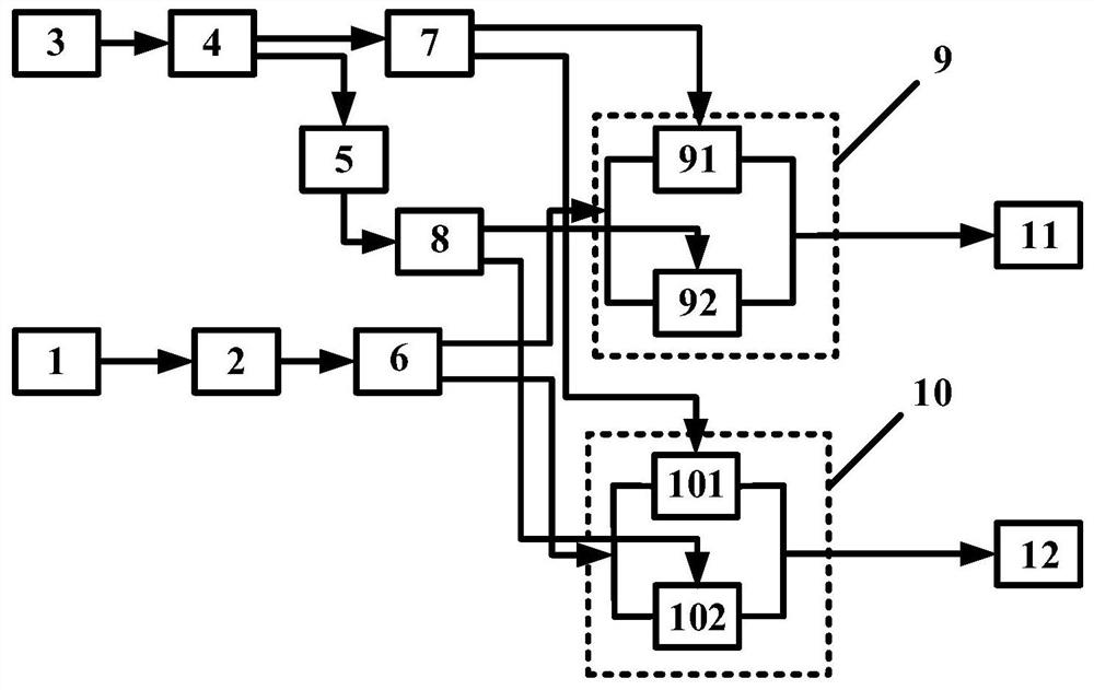
[0030]The output end of the continuous wave laser 1 is connected to the input end of the polarization controller 2, the output end of the polarization controller 2 is connected to the input end of the optical power splitter 6, and the output ends of the optical power splitter 6 are respectively connected to the I / Q modulator 9 The optical input end and the optical input end of the I / Q modulator 10, the output end of the signal generator 3 is connected to the input end of the electric power splitter 4, and the output end of the electric power splitter 4 is respectively connected to the input end of the electric power splitter 7 and the input end of the electric delay line 5, the output end of the electric delay line 5 is connected to the input end of the electric power divider 8, and the output end of the electric power divider 7 is connected to the radio frequency input end and the single drive Mach-Zehnder modulator 91 respectively. The RF input end of the Mach-Zehnder modulat...
Embodiment 2
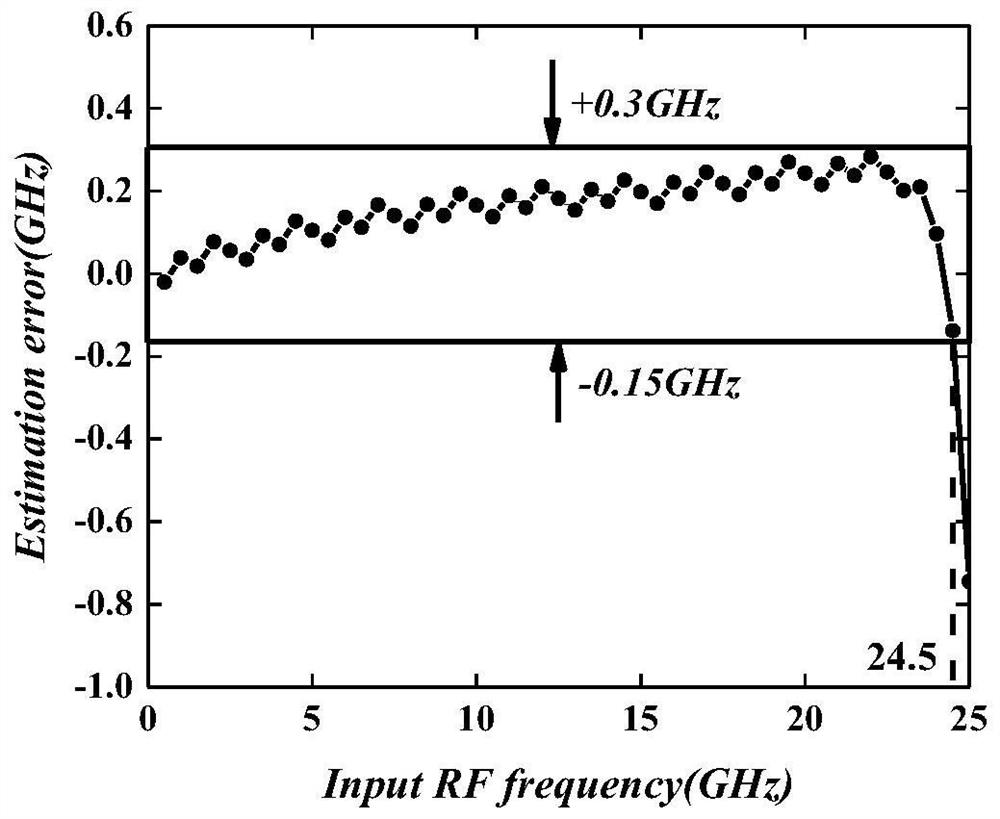
[0035] The output end of the continuous wave laser 1 is connected to the input end of the polarization controller 2, the output end of the polarization controller 2 is connected to the input end of the optical power splitter 6, and the output ends of the optical power splitter 6 are respectively connected to the I / Q modulator 9 The optical input end and the optical input end of the I / Q modulator 10, the output end of the signal generator 3 is connected to the input end of the electric power splitter 4, and the output end of the electric power splitter 4 is respectively connected to the input end of the electric power splitter 7 and the input end of the electric delay line 5, the output end of the electric delay line 5 is connected to the input end of the electric power divider 8, and the output end of the electric power divider 7 is connected to the radio frequency input end and the single drive Mach-Zehnder modulator 91 respectively. The RF input end of the Mach-Zehnder modula...
Embodiment 3
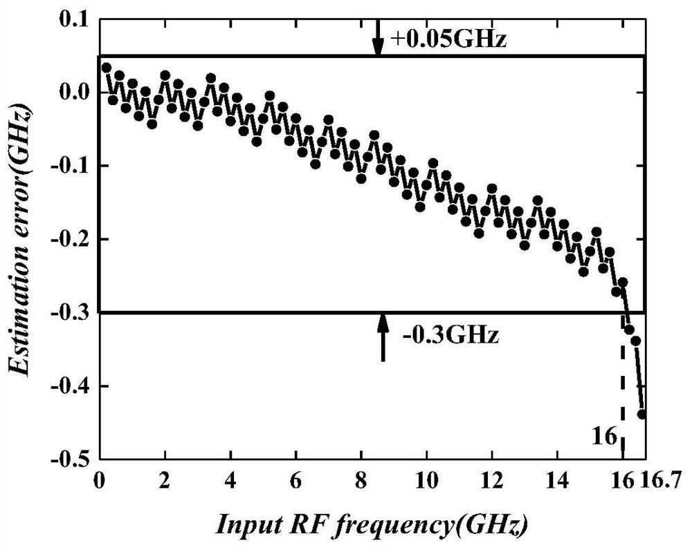
[0040] The output end of the continuous wave laser 1 is connected to the input end of the polarization controller 2, the output end of the polarization controller 2 is connected to the input end of the optical power splitter 6, and the output ends of the optical power splitter 6 are respectively connected to the I / Q modulator 9 The optical input end and the optical input end of the I / Q modulator 10, the output end of the signal generator 3 is connected to the input end of the electric power splitter 4, and the output end of the electric power splitter 4 is respectively connected to the input end of the electric power splitter 7 and the input end of the electric delay line 5, the output end of the electric delay line 5 is connected to the input end of the electric power divider 8, and the output end of the electric power divider 7 is connected to the radio frequency input end and the single drive Mach-Zehnder modulator 91 respectively. The RF input end of the Mach-Zehnder modula...
PUM
 Abstract
Description
Claims
Application Information
 - R&D
- Intellectual Property
- Life Sciences
- Materials
- Tech Scout
- Unparalleled Data Quality
- Higher Quality Content
- 60% Fewer Hallucinations
Browse by: Latest US Patents, China's latest patents, Technical Efficacy Thesaurus, Application Domain, Technology Topic, Popular Technical Reports.
© 2025 PatSnap. All rights reserved.Legal|Privacy policy|Modern Slavery Act Transparency Statement|Sitemap|About US| Contact US: help@patsnap.com


