Supercharge Your Innovation With Domain-Expert AI Agents!

Laser machining positioning mechanism for special-shaped metal tubes

A special-shaped metal and laser processing technology, applied in metal processing, metal processing equipment, laser welding equipment, etc., can solve the problems of increased labor costs, high costs, and easy measurement errors, etc., to achieve accurate positioning, reduce labor costs, and reduce processing cost effect

Active Publication Date: 2021-10-26
广东镭泰激光智能装备有限公司
View PDF9 Cites 0 Cited by
  • Summary
  • Abstract
  • Description
  • Claims
  • Application Information

AI Technical Summary

Problems solved by technology

Disadvantages of this method are: 1) First laser cutting out a pre-reference, one more laser processing, high cost; 2) Measuring size L1, easy to measure errors, resulting in NG products; 3), more measuring processes, Calculating the process is not conducive to automatic processing and increases labor costs
[0003] In the petroleum, chemical, precision hardware, aerospace, medical and 3C industries, the application of many products requires high processing quality for the shape of metal pipe parts, such as pipes with inclined planes, square pipes that become round, and other special-shaped pipes. Dimensional accuracy requirements are getting higher and higher, and the traditional method of clamping pipes cannot meet its quality requirements

Method used


Image

  • Laser machining positioning mechanism for special-shaped metal tubes
  • Laser machining positioning mechanism for special-shaped metal tubes
  • Laser machining positioning mechanism for special-shaped metal tubes

Examples


Embodiment

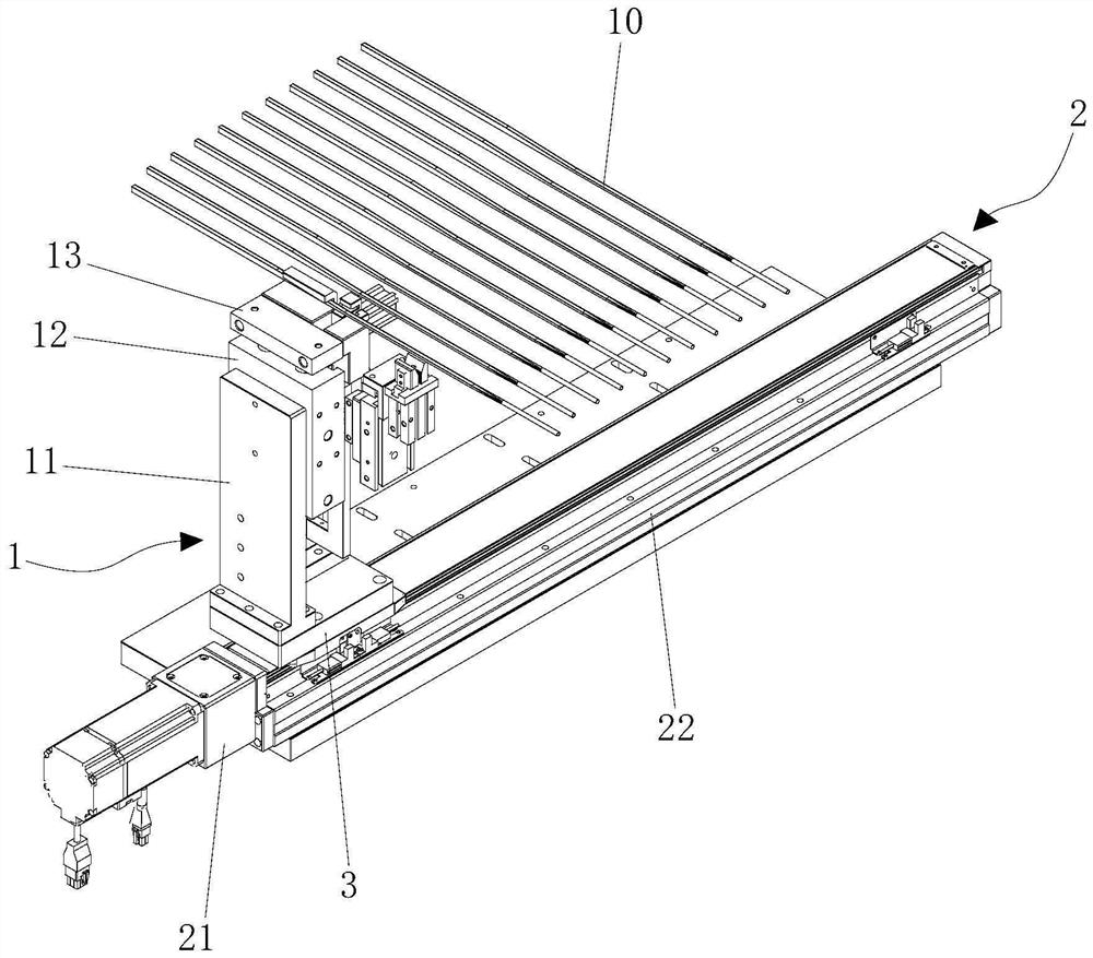
[0030] The embodiment of the present invention provides a special-shaped metal tube laser processing positioning mechanism, which is specially used for clamping and positioning special-shaped metal tubes during laser processing. By taking the special-shaped part of the pipe as a reference, the pipe is installed in place, positioned, and clamped. , and then laser processing. Through the mechanism, the laser processing procedure can be reduced, the laser processing man-hour can be shortened, automatic production can be realized, the yield rate of product processing can be improved at the same time, and the product processing cost can be reduced.

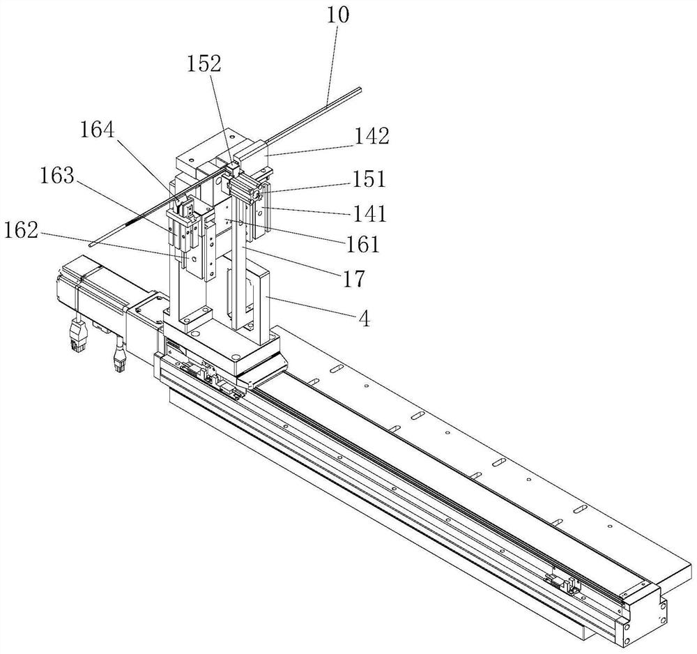
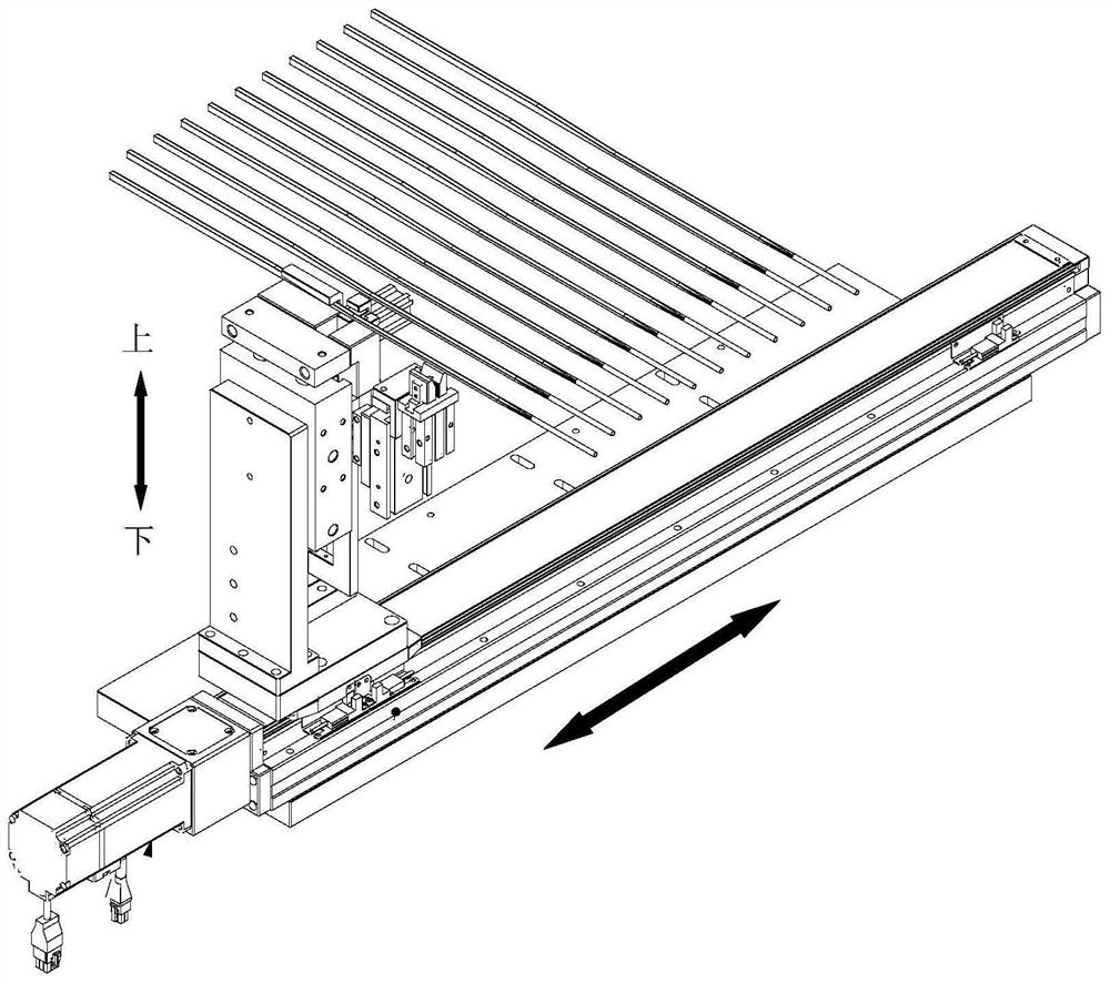
[0031] see figure 1 , figure 2 , the mechanism mainly includes a positioning component 1 and a moving component 2. The positioning component 1 is movably arranged on the moving component 2. The moving component 2 can drive the positioning component 1 to move. The positioning component 1 completes the positioning and clamping of the s...


PUM


Abstract

The invention discloses a laser machining positioning mechanism for special-shaped metal tubes. The laser machining positioning mechanism for the special-shaped metal tubes comprises a positioning assembly and a moving assembly, the positioning assembly is movably arranged on the moving assembly, the moving assembly can drive the positioning assembly to move, the positioning assembly completes positioning and clamping of the special-shaped metal tubes, the positioning assembly comprises a mounting plate, an upward ejecting device, a connecting plate, a pre-positioning device, a positioning device, a clamping device and an L-shaped limiting block, the upward ejecting device is arranged on the mounting plate, the driving end of the upward ejecting device faces upwards and is provided with the connecting plate, the connecting plate can move up and down under driving of the upward ejecting device, and the pre-positioning device, the positioning device and the clamping device are installed on one side of the connecting plate and are sequentially arranged in the length direction of the special-shaped metal pipes. The invention provides the laser machining positioning mechanism for the the special-shaped metal pipes and special for the special-shaped metal pipes, through the mechanism, laser machining procedures can be reduced, laser machining working hours can be shortened, automatic production can be achieved, meanwhile, the product machining yield is increased, and the product machining cost is reduced.

Description

technical field [0001] The invention relates to the field of laser processing, in particular to a positioning mechanism for laser processing of special-shaped metal tubes. Background technique [0002] With the development and progress of the times, the requirements for processing dimensional accuracy of pipe products are getting higher and higher; such pipes are widely used in petroleum, chemical, precision hardware, aerospace, medical and 3C industries; these pipes are processed and clamped, and their size positioning , Generally, a three-jaw chuck is used to hold the pipe, and one end face of the pipe is laser cut first, and the other part of the pipe is processed based on this end face. If the incoming pipe is a special-shaped pipe, and the size from the special-shaped part of the pipe to the end surface of the pipe is inconsistent, and the tolerance of the incoming material is between 0.1--100mm, this method is required for pipes that require a processing tolerance of ≤...

Claims


Application Information

Patent Timeline
IPC IPC(8): B23K26/38B23K26/02B23K26/08B23K101/06
CPCB23K26/38B23K26/02B23K26/083B23K2101/06
Inventor 肖磊龚成万张善基李斌
Owner 广东镭泰激光智能装备有限公司
Features
  • R&D
  • Intellectual Property
  • Life Sciences
  • Materials
  • Tech Scout
  • Unparalleled Data Quality
  • Higher Quality Content
  • 60% Fewer Hallucinations
Learn More