Protective ceiling
A technology of ceiling and side panels, which is applied in the direction of roof, general water supply saving, building components, etc. It can solve the problems of unfavorable processing and production, not easy to breathe, and affect the reception of sunlight, so as to improve efficiency and ensure air permeability.
- Summary
- Abstract
- Description
- Claims
- Application Information
AI Technical Summary
Problems solved by technology
Method used
Image

Examples
Embodiment 1
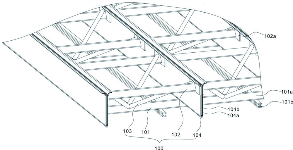
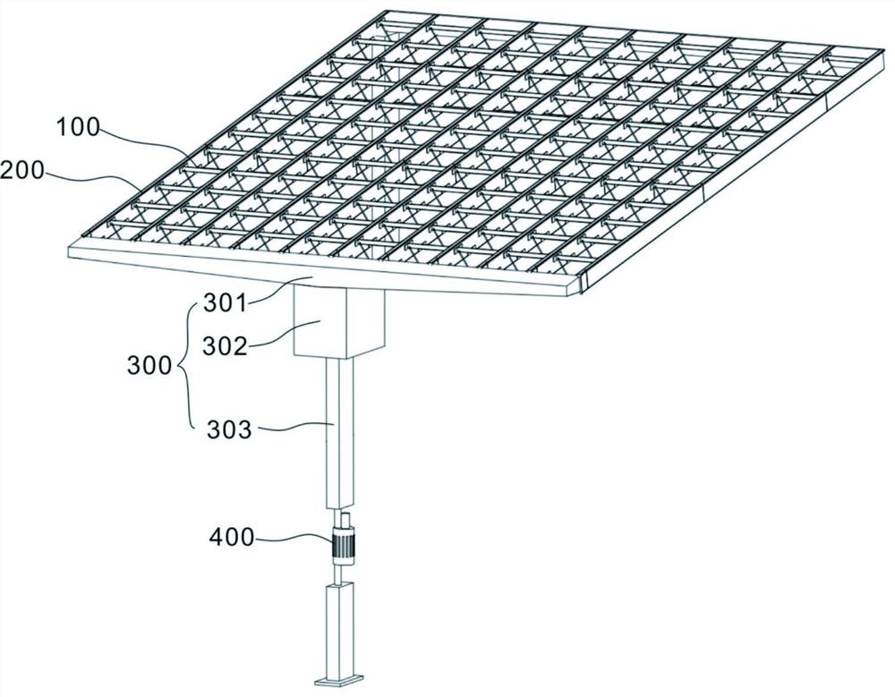
[0032] Refer Figure 1 ~ 5 with Figure 11 For the first embodiment of the present invention, this embodiment provides a protective ceiling comprising a support member 100, a protective member 200, a collecting member 300.
[0033]The support member 100 includes a fixing frame 101, a support rod 102, a lever 103, and a base 104. Two sets of side plates 104a are provided on the base 104, and the base 104 is integrally formed or fixed to the side plate 104a, and there is a housing groove 104b between the side plate 104a, and the two sets of side plate 104a are symmetrically distributed on both sides of the accommodating groove 104b, side. The plate 104a and the accommodating groove 104b are vertically provided with several pass grooves 104c, the pass groove 104c vertically penetrate the side plate 104a and the receiving groove 104b bottom, and the tie rod 103 is disposed on the fixing frame 101, and the tie rod 103 is fixed between the fastener 101 Connecting, the tie rod 103 is conne...
Embodiment 2
[0037] Refer Figure 1 ~ 6 with Figure 10 For a second embodiment of the present invention, the embodiment is inclined downward from the upper side of the collecting member 300, which is advantageous for guiding rainwater to accumulate. The mount 101 includes a plurality of crossbar 101a and a plurality of joysticks 101b, and the crossbar 101a is disposed parallel to the support rod 102, and the longitudinal rod 101b is provided perpendicular to the crossbar 101a, and the crossbar 101a and the lens 101b form a mesh shape, fixed connection. Together, it is advantageous to improve the structural strength of the housing 101, while reducing self weight. The support rod 102 is connected to the side plate 102a on the side of the fixing plate 102a, and the other side of the fixing plate 102a is connected to the side plate 104a. The tie rod 103 is provided, and each of the tensile rods 103 is disposed on the fixed plate 102a, and the other end is disposed on the crossbar 101a, the fixing p...
Embodiment 3
[0047] Refer Figure 7 ~ 11 For a third embodiment of the present invention, this embodiment is based on two embodiments.
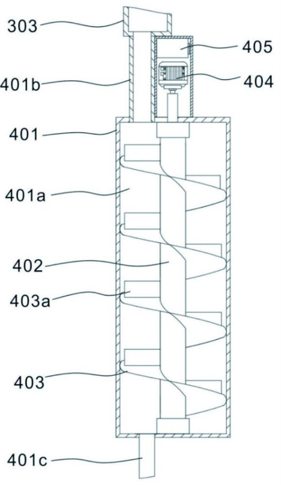
[0048] Please refer to Figure 10 The power generation component 400 is also included, and the power generating component 400 includes a housing 401, a mandrel 402, a screw plate 403, a generator 404, and a battery 405. The housing 401 is provided with a receiving cavity 401a, and the top of the outer casing 401 is connected to the water pipe 401b and the flow pipe 303 away from the water storage tank 302, so that the water in the flow pipe 303 enters the water storage tank 302 through the water pipe 401b through the water pipe 302 The inner; the outer casing 401 is connected to the water pipe 401c, facilitating the discharge of water in the water storage tank 302 by the water pipe 401c; the water pipe 401b and the water pipe 401c communicate with the housing cavity 401a, the mandrel 402 rotates to be disposed in the upper wall of the accommodating cavity 401a ...
PUM
 Abstract
Description
Claims
Application Information
 - R&D Engineer
- R&D Manager
- IP Professional
- Industry Leading Data Capabilities
- Powerful AI technology
- Patent DNA Extraction
Browse by: Latest US Patents, China's latest patents, Technical Efficacy Thesaurus, Application Domain, Technology Topic.
© 2024 PatSnap. All rights reserved.Legal|Privacy policy|Modern Slavery Act Transparency Statement|Sitemap