
Fuel nozzle and gas turbine

A fuel nozzle and fuel technology, which is applied in combustion chambers, combustion methods, combustion equipment, etc., can solve the problems of increased nitrogen oxide emissions, and achieve the effects of reducing emissions, rapidly and uniformly blending, and improving thermal protection performance.

Active Publication Date: 2021-10-26
CHINA UNITED GAS TURBINE TECH CO LTD
View PDF7 Cites 0 Cited by
  • Summary
  • Abstract
  • Description
  • Claims
  • Application Information

AI Technical Summary

Problems solved by technology

At present, advanced gas turbine combustors are constantly developing towards high temperature rise and low pollution. The higher the temperature of the gas in the combustion chamber, the more conducive to the improvement of efficiency and power. However, high temperature and oxygen enrichment will lead to nitrogen oxides NO x Emissions have risen sharply

Method used


Image

  • Fuel nozzle and gas turbine
  • Fuel nozzle and gas turbine
  • Fuel nozzle and gas turbine

Examples


Embodiment Construction

[0037] Embodiments of the invention are described in detail below, examples of which are illustrated in the accompanying drawings. The embodiments described below by referring to the figures are exemplary and are intended to explain the present invention and should not be construed as limiting the present invention.

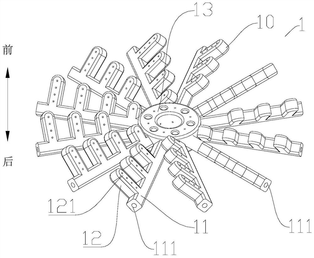
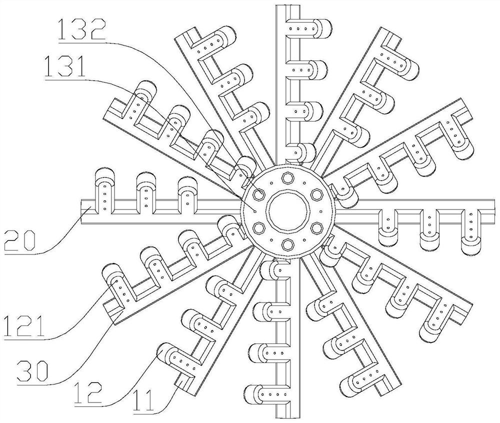
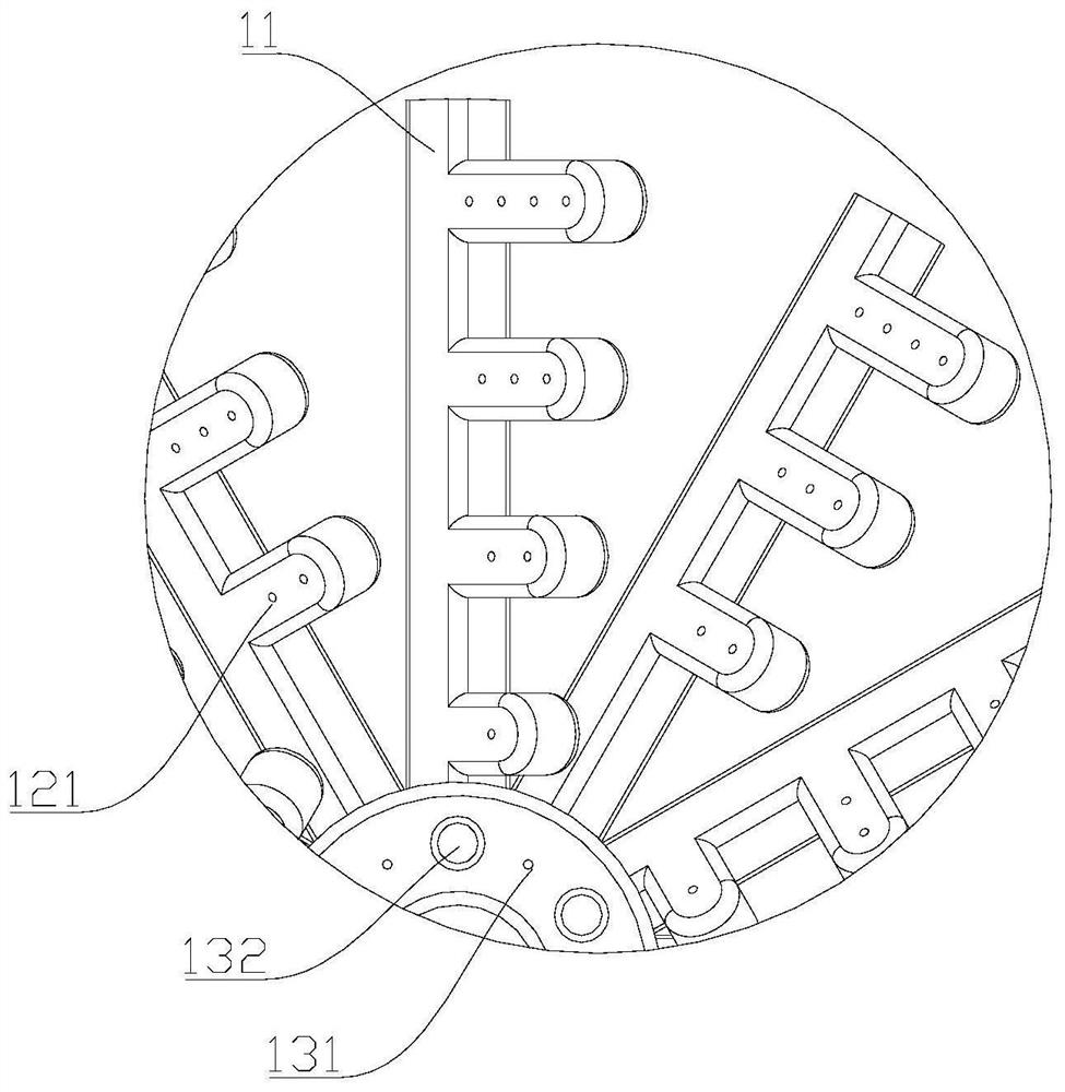
[0038] The following is based on Figure 1-Figure 4 The fuel nozzle 1 of the embodiment of the present invention is described. The fuel nozzle 1 includes several fuel pipe assemblies 10, each fuel pipe assembly 10 includes a fuel pipe 11, and the fuel pipe 11 has a fuel passage for fuel to flow therein. Several fuel pipes 11 are radially arranged around the axis of the fuel nozzle 1 , and the fuel pipes 11 are provided with fuel inlets 111 communicating with the fuel passages. Each fuel pipe assembly 10 is also provided with a fuel nozzle 121 communicating with the fuel passage, and the ejection direction of the fuel nozzle 121 is forward. Fuel enters the fuel...


PUM


Abstract

The invention provides a fuel nozzle and a gas turbine. The fuel nozzle comprises a plurality of fuel pipe assemblies. Each fuel pipe assembly comprises a fuel pipe. A fuel channel is formed in each fuel pipe. The multiple fuel pipes are arranged in a radial shape with the axis of the fuel nozzle as the center. Each fuel pipe is provided with a fuel inlet communicating with the corresponding fuel channel. Each fuel pipe assembly is further provided with a fuel nozzle communicating with the corresponding fuel channel. The spraying direction of the fuel nozzles is forward. Rapid and uniform mixing of fuel and air can be achieved within a short time, the emission amount of NOx is reduced, the influence on the flow loss of a combustion chamber is small, and the performance of the combustion chamber can be effectively improved.

Description

technical field [0001] The invention relates to the technical field of gas turbines, in particular to a fuel nozzle and a gas turbine. Background technique [0002] A gas turbine is a heat engine that uses continuously flowing gas as a working medium to drive the impeller to rotate at high speed and convert the thermal energy of the fuel into mechanical work. The core components of a gas turbine include three main parts: a compressor, a combustion chamber, and a turbine. After the air is pressurized by the compressor, it enters the combustion chamber and is mixed with fuel for combustion. The hot gas generated drives the turbine to do work. As one of the three core components, the combustion chamber plays a decisive role in the performance of the entire gas turbine. At present, advanced gas turbine combustors are constantly developing towards high temperature rise and low pollution. The higher the temperature of the gas in the combustion chamber, the more conducive to the i...

Claims


Application Information

Patent Timeline
IPC IPC(8): F23R3/38
CPCF23R3/38
Inventor 静大亮赵光军毛荣海
Owner CHINA UNITED GAS TURBINE TECH CO LTD
Learn More