Fan blade surface crack monitoring device and method and induction material coating method

A technology for surface cracks and fan blades, applied in the field of blades, can solve the problems of ineffective monitoring, difficult maintenance, large crack size, etc., to achieve the effect of effective monitoring and ensuring accuracy

Pending Publication Date: 2021-10-26
无锡风电设计研究院有限公司
View PDF1 Cites 0 Cited by
  • Summary
  • Abstract
  • Description
  • Claims
  • Application Information

AI Technical Summary

Problems solved by technology

[0003] However, there are many defects in the above-mentioned existing monitoring methods: noise monitoring refers to the installation of acoustic sensors at the bottom of the engine room or the tower, and the noise of the blades is monitored through the acoustic sensors. The monitoring method is for structural cracks caused by the bearing of the blade root. The linear velocity in the crack area is small, and the crack opening is not obvious, so it cannot be effectively monitored.
[0006] Headroom monitoring mainly judges the torsional deformation of blades through image headroom monitoring. The distance between the blade and the suction surface of the blade is used to judge the torsional state of the blade, so as to judge whether the torsional deformation of the blade is too large, but it is mainly used to detect the torsional deformation of the blade tip, blade center, and maximum chord length. For Blade cracks cannot be monitored accurately in real time. When the impact of cracks can be identified in the distance from the blade tip, the size of the cracks generated at this time is relatively large, the blade is on the verge of breaking, and maintenance is difficult

Method used


Image

  • Fan blade surface crack monitoring device and method and induction material coating method
  • Fan blade surface crack monitoring device and method and induction material coating method
  • Fan blade surface crack monitoring device and method and induction material coating method

Examples


Embodiment Construction

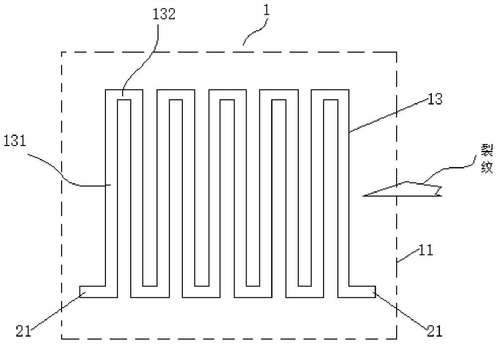
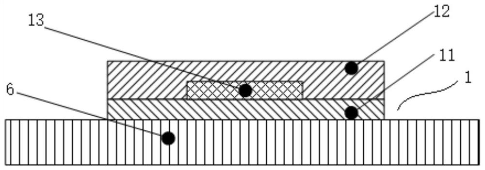
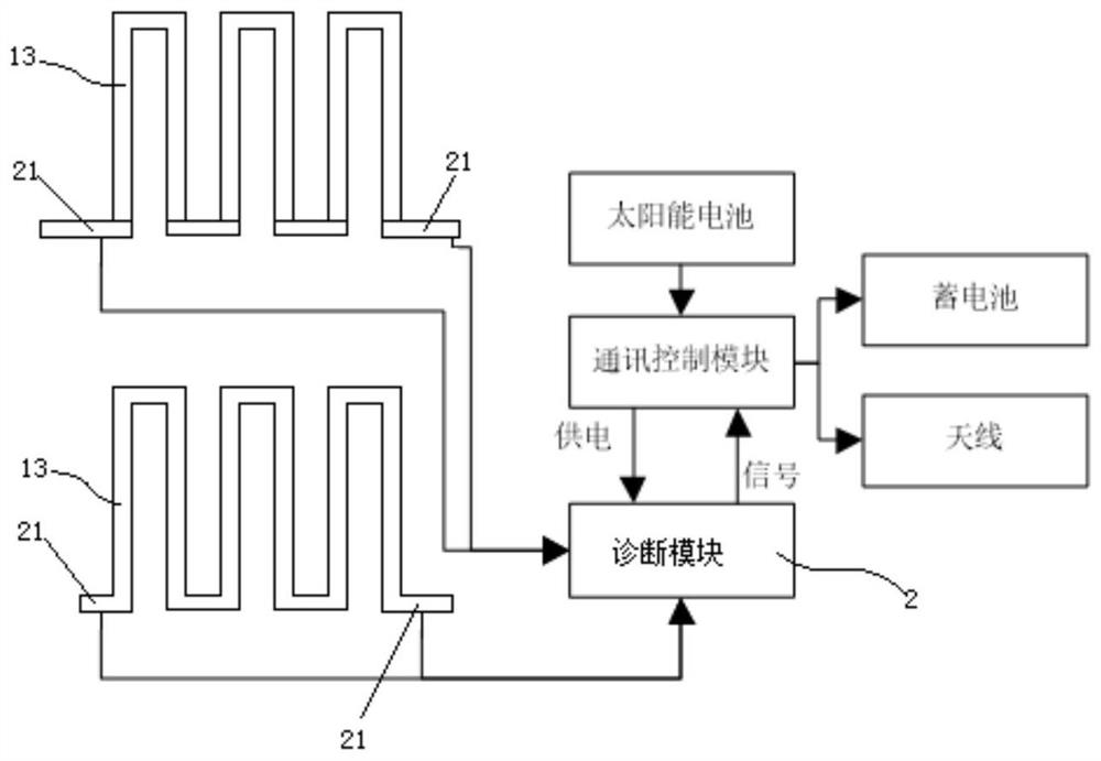
[0050] See figure 1 , figure 2 , image 3 , Figure 4 , a fan blade surface crack monitoring device, which includes a number of induction coatings 1 coated on the blade surface, a diagnostic module 2, a power supply 3 and a communication control module 4, the power supply 3 is electrically connected to the diagnostic module 2, and is used to give the diagnostic module 2 for power supply, and the diagnosis module 2 communicates with the external terminal 5 through the communication control module 3, and the external terminal 5 is a central control system or a remote monitoring system. The diagnostic module 2, power supply 3 and communication control module 4 are welded and fixed on the flexible board or PCB, packaged and fixed on the surface of the blade root or inside the blade, or integrated in the control box and installed on a suitable position such as the blade root cover.

[0051] The power supply 3 includes an external power supply and an internal power supply. The e...


PUM


Abstract

The invention discloses a fan blade surface crack monitoring device and monitoring method and an induction material coating method. A blade can be prevented from being seriously damaged due to the fact that cracks are too large; the monitoring device comprises induction coating layers, a diagnosis module and a power source, and each induction coating layer comprises a first insulating layer, electrically conductive layers and a second insulating layer; the electrically conductive layers are distributed in a to-be-monitored area in a roundabout structure or a grid structure to form a plurality of induction coating layer areas, and each induction coating layer area is electrically connected with the diagnosis module. The monitoring method comprises the steps that: the to-be-monitored area on the surface of the blade is divided into a plurality of sub-areas, and the surface of each sub-area is coated with the induction coating layer; and the electrically conductive layers in the induction coating layers are electrically connected with the diagnosis module, whether the electrically conductive layers are powered off or not is detected through the diagnosis module, if the electrically conductive layers are powered off, it is indicated that cracks exist in the sub-areas, the diagnosis module gives an alarm, and meanwhile power-off information is sent to an external terminal. The coating method of the induction coating layer comprises the step of sequentially coating the first insulating layer, the electrically conductive layer and the second insulating layer on the to-be-monitored area on the surface of the blade.

Description

technical field [0001] The invention relates to the technical field of blades, in particular to a device and method for monitoring cracks on the surface of fan blades and a coating method for inductive materials. Background technique [0002] Wind turbines have high requirements on the strength of blades, but due to the influence of blade structure, material, operating frequency, processing technology, operating environment and other factors, it is very easy to cause cracks on the surface of wind turbine blades. The appearance of cracks seriously reduces the anti-strain ability and service life of the blade. Therefore, in the process of using wind turbines to generate electricity, it is necessary to monitor the surface of the blades. Currently commonly used monitoring methods include: noise monitoring, vibration monitoring, strain monitoring, clearance monitoring, etc. [0003] However, there are many defects in the above-mentioned existing monitoring methods: noise monito...

Claims


Application Information

Patent Timeline
Patent Type & Authority Applications(China)
IPC IPC(8): G01N27/00G01N27/04G01N27/20G01B7/02B05D1/38B05D5/00B05D5/12B05D7/00B05D7/26
CPCG01N27/00G01N27/041G01N27/20G01B7/02B05D5/00B05D5/12B05D5/066B05D7/26B05D7/574B05D7/576B05D1/38
Inventor 包洪兵俞志强冯玥枫陈程李丹管彩文陆凡
Owner 无锡风电设计研究院有限公司
Why Eureka
Try Eureka