
Laser beam combining device, combined stepped reflector thereof and filling rate calculation method

A mirror and combined technology, which is applied in the direction of laser devices, semiconductor laser devices, lasers, etc., can solve the problems of increased production costs, increased overall thickness and weight of integrated stepped mirrors, and unfavorable system integration.

Inactive Publication Date: 2021-10-26
KEY & CORE TECH INNOVATION INST OF THE GREATER BAY AREA
View PDF8 Cites 2 Cited by
  • Summary
  • Abstract
  • Description
  • Claims
  • Application Information

AI Technical Summary

Problems solved by technology

[0003] However, due to the need to ensure sufficient physical distance between the laser chips to ensure the heat dissipation effect, thereby ensuring the maximum power and the service life of the laser, when the first method is used to increase the filling rate, the laser can only be reduced within a certain range. The physical spacing of chips has great limitations, and the extent to which it can be improved is limited
There are two types of stepped reflectors used in the second method, one is the integrated stepped reflector, and its disadvantages include: the structure of the integrated stepped reflector is designed to reflect the laser beam in the thickness direction, which is difficult to process, resulting in The processing cost is high, and it is difficult to meet the high-precision requirements; at the same time, the overall thickness and weight of the integrated stepped mirror will increase significantly, which is not conducive to miniaturized system integration
In addition, due to the shape of the integrated step, when polishing the reflective surface used to reflect the laser beam, the direction is single, the finish of the reflective surface is low, and the parallelism error between each reflective surface is large
Low finish and large parallelism errors increase losses and reduce reflectivity
In addition, the one-piece structure cannot adapt to the pointing error of different laser chip packages, and it will also increase loss and reduce reflectivity
The other is a stepped reflector composed of separate reflectors, each of which exists independently. However, since each separate reflector has a different shape, it needs to be individually customized, the structure becomes complicated, and the production cost will increase significantly
[0004] Therefore, in general, the existing two methods have limitations and many defects, and cannot meet the needs of improving the filling rate of the laser beam.

Method used


Image

  • Laser beam combining device, combined stepped reflector thereof and filling rate calculation method
  • Laser beam combining device, combined stepped reflector thereof and filling rate calculation method
  • Laser beam combining device, combined stepped reflector thereof and filling rate calculation method

Examples


Embodiment Construction

[0040] The following description serves to disclose the present invention to enable those skilled in the art to carry out the present invention. The preferred embodiments described below are only examples, and those skilled in the art can devise other obvious variations. The basic principles of the present invention defined in the following description can be applied to other embodiments, variations, improvements, equivalents and other technical solutions without departing from the spirit and scope of the present invention.

[0041]Those skilled in the art should understand that, in the disclosure of the present invention, the terms "vertical", "transverse", "upper", "lower", "front", "rear", "left", "right", The orientations or positional relationships indicated by "vertical", "horizontal", "top", "bottom", "inner", "outer", etc. are based on the orientation or positional relationship shown in the drawings, which are only for the convenience of describing the present inventio...


PUM

PropertyMeasurementUnit
thicknessaaaaaaaaaa
thicknessaaaaaaaaaa
wavelengthaaaaaaaaaa

Abstract

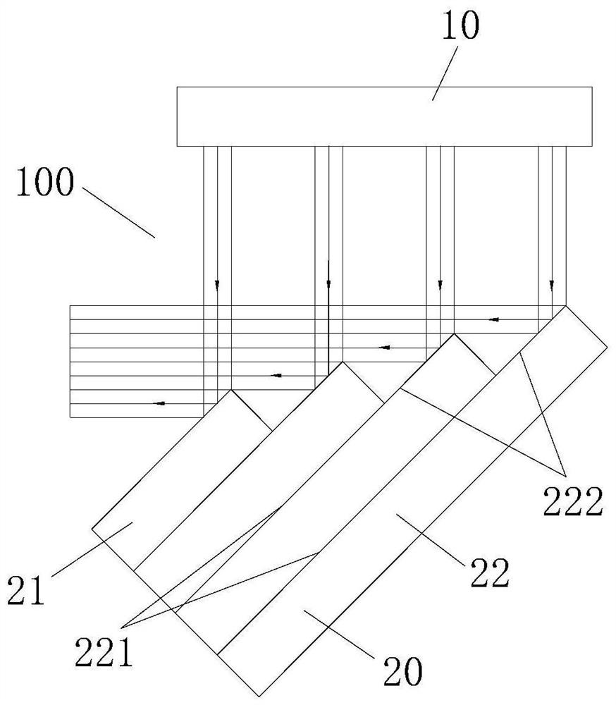
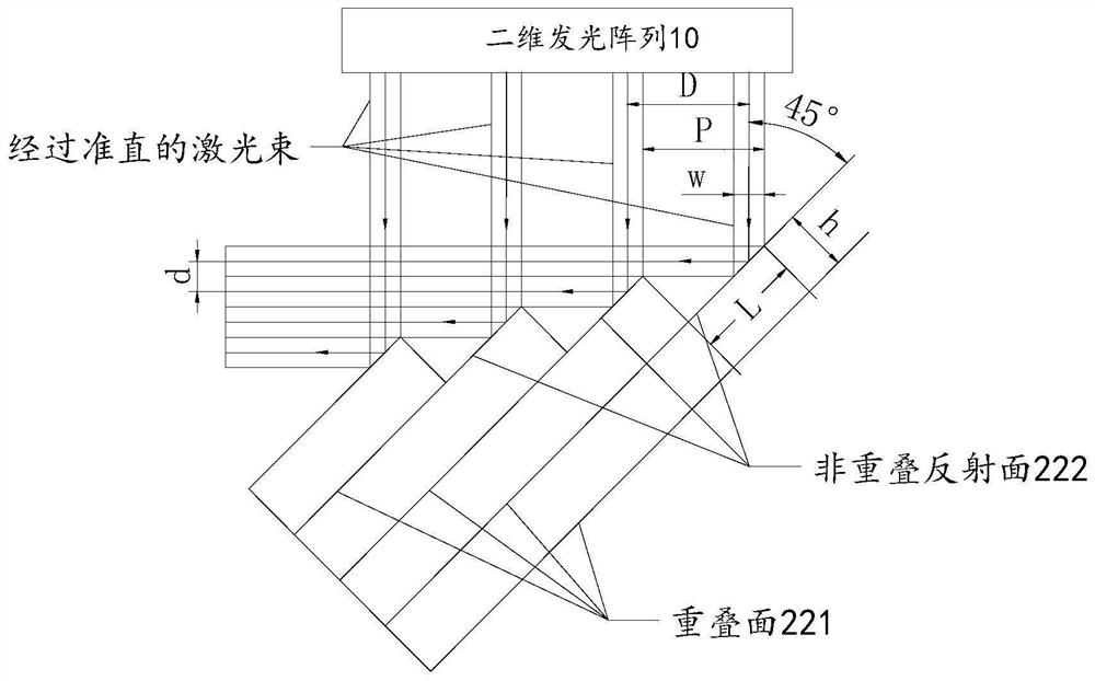
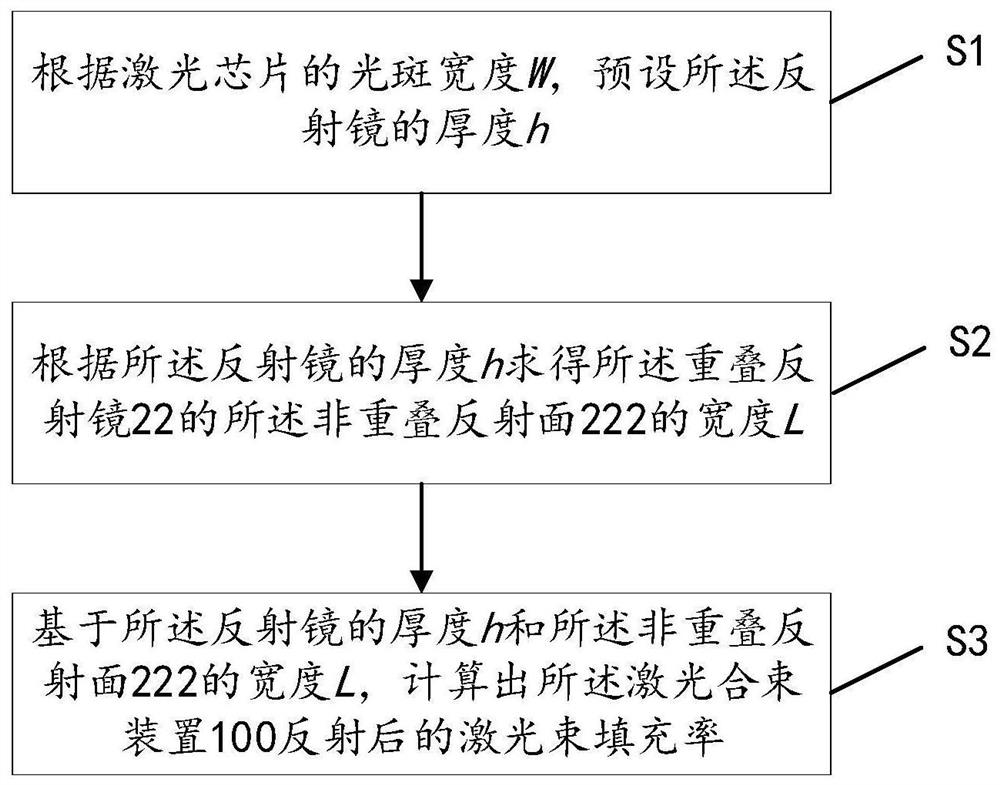
The invention relates to a laser beam combining device and a combined stepped reflector and a filling rate calculation method thereof. The laser beam combining device comprises a two-dimensional light-emitting array and the combined stepped reflector, the combined step reflector is used for reflecting a plurality of laser beams emitted by the two-dimensional light-emitting array, the combined stepped reflecting mirror is formed by sequentially overlapping a plurality of reflecting mirrors which are the same in length and gradually increased in width, and the center distance of laser beams reflected by the combined stepped reflecting mirror is smaller than the center distance before incidence, so that the filling rate of the laser beams emitted by the two-dimensional light-emitting array can be increased; and the invention further provides a filling rate calculation method of the laser beam combining device, the step width of the combined stepped reflecting mirror is obtained according to the light spot width of the laser chip and the thickness of the preset reflecting mirror, the filling rate of the laser beam is finally obtained through calculation, and the calculation method for engineering application is provided.

Description

technical field [0001] The invention relates to the technical field of semiconductor lasers, in particular to a laser beam combining device, a combined stepped reflector and a filling rate calculation method. Background technique [0002] In order to adapt to a larger application range, it is necessary to continuously improve the optical power density of the laser. To increase the optical power density, it is necessary to increase the filling rate of the laser beam. At present, there are mainly two ways to increase the filling rate of the laser beam. The first way is to increase the filling rate of the laser beam by placing more laser chips per unit area. Specifically, by reducing the physical distance between the laser chips , accommodate more laser chips in the same area, thereby increasing the filling rate. The second way is to reduce the laser beam spacing by placing stepped reflectors in the light output direction on the basis of retaining the physical spacing of the ...

Claims


Application Information

Patent Timeline
Patent Type & Authority Applications(China)
IPC IPC(8): G02B27/14G02B27/00H01S5/40
CPCG02B5/09G02B27/14G02B27/0012H01S5/4012H01S5/4075
Inventor 何秋婷扈金富冯水松印晓丽
Owner KEY & CORE TECH INNOVATION INST OF THE GREATER BAY AREA
Learn More