Movable magnetic steel type self-driven magnetic levitation guide rail device and control method thereof
A technology of a guide rail device and a control method, which is applied in the field of a moving magnet steel type self-driven maglev guide rail device and its control field, can solve the problems that the guide rail cannot be self-driven, cannot actively adjust the gap with multiple degrees of freedom, and is difficult to guarantee high rigidity and straightness. , to achieve the effect of ensuring high rigidity, improving performance indicators, and simple and compact structure
- Summary
- Abstract
- Description
- Claims
- Application Information
AI Technical Summary
Problems solved by technology
Method used
Image
Examples
specific Embodiment approach 1
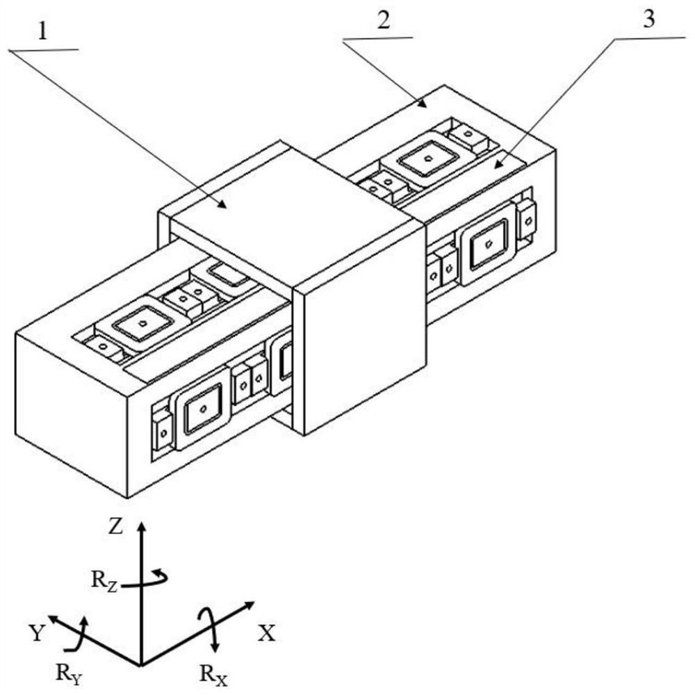
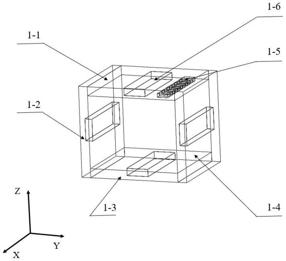
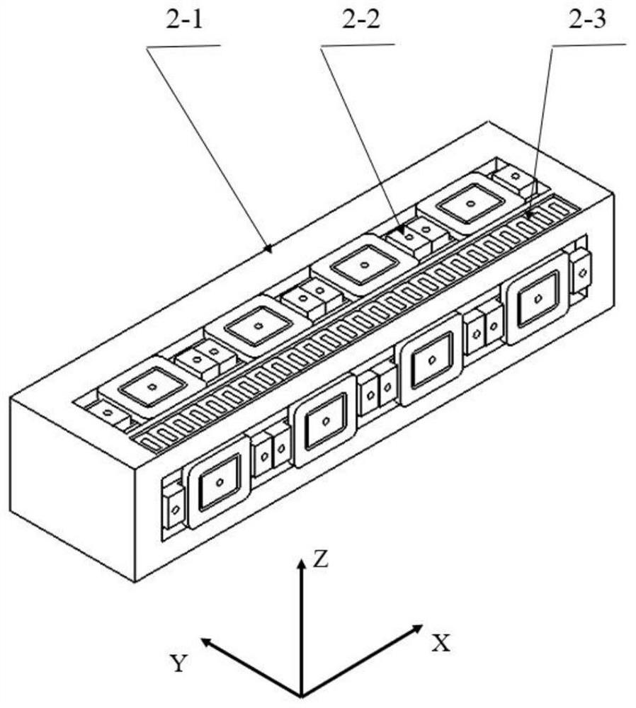
[0028] Specific implementation mode one: as Figure 1-Figure 4As shown, this embodiment discloses a moving magnet steel type self-driven maglev guide rail device, including a guide sleeve 1 and a guide shaft 2; the guide sleeve 1 is sleeved on the guide shaft 2; the guide sleeve 1 includes a permanent magnet 1-5, four guide sleeve support frames and four I-type electromagnets 1-6; the guide shaft 2 includes a guide shaft support frame 2-1, a coil winding 2-3 and a plurality of E-shaped components 2-2; Each of the E-shaped components 2-2 includes a primary coil 2-2-1, an induction coil 2-2-2, a bipolar electromagnet 2-2-3, an eddy current sensor 2-2-4 and two Hall Er element 2-2-5;
[0029] The four guide sleeve support frames are combined to form a square sleeve, and the middle parts of the four guide sleeve support frames are respectively packaged with I-type electromagnets 1-6, and the four I-type electromagnets 1-6 are all along the length direction of the guide shaft 2 A...
specific Embodiment approach 2
[0034] Specific implementation mode two: as Figure 1-Figure 4 As shown, this embodiment discloses a control method for realizing a moving magnet steel type self-driving maglev guide rail using the moving magnet steel type self-driving maglev guide rail device described in the specific embodiment, the control method is:
[0035] By adjusting the current size of the primary coils 2-2-1 of multiple E-type components 2-2 packaged on the upper and lower sides of the guide shaft 2, the primary coils 2-2-1 of multiple E-type components 2-2 on the same side are required to 1. The magnitude of the current should be the same (the magnitude of the current of the primary coil 2-2-1 of the multiple E-shaped components 2-2 on the upper and lower sides is different), so that the adjustment of the 1Z degree of freedom of the guide sleeve can be realized;
[0036] Adjust the current size of the primary coils 2-2-1 of multiple E-type components 2-2 packaged on the left and right sides of the g...
PUM
 Abstract
Description
Claims
Application Information
 - R&D
- Intellectual Property
- Life Sciences
- Materials
- Tech Scout
- Unparalleled Data Quality
- Higher Quality Content
- 60% Fewer Hallucinations
Browse by: Latest US Patents, China's latest patents, Technical Efficacy Thesaurus, Application Domain, Technology Topic, Popular Technical Reports.
© 2025 PatSnap. All rights reserved.Legal|Privacy policy|Modern Slavery Act Transparency Statement|Sitemap|About US| Contact US: help@patsnap.com


