Stamping device for metal base plate production

A stamping device and metal substrate technology, applied in the field of metal substrate stamping, can solve the problems of increasing the labor intensity of workers to clean up scraps, reducing the environmental sanitation of the workplace, and the scraps are easy to hurt workers, etc., to reduce the cleaning workload, It is easy to clamp and disassemble the lower mold and avoid the effect of crushing

Inactive Publication Date: 2021-10-29
深圳市建宏达照明电路有限公司
View PDF1 Cites 6 Cited by
  • Summary
  • Abstract
  • Description
  • Claims
  • Application Information

AI Technical Summary

Problems solved by technology

[0005] In order to solve the above-mentioned technical problems, the present invention provides a stamping device for metal substrate production to solve the problem that the stamping head is easy to crush the staff when the staff is loading and unloading at the bottom of the stamping head. The bottom loading and unloading space is small, which is not convenient for the staff to operate, and when the current stamping device is in use, the scraps after stamping are prone to splash, and the splashed scraps are easy to hurt the staff on the one hand, and on the other hand Reduce the environmental sanitation of the workplace, increase the labor intensity of the staff to clean up the debris, and reduce the problem of work efficiency

Method used


Image

  • Stamping device for metal base plate production
  • Stamping device for metal base plate production
  • Stamping device for metal base plate production

Examples


Embodiment 1

[0034] as attached figure 1 to attach Figure 14 Shown:

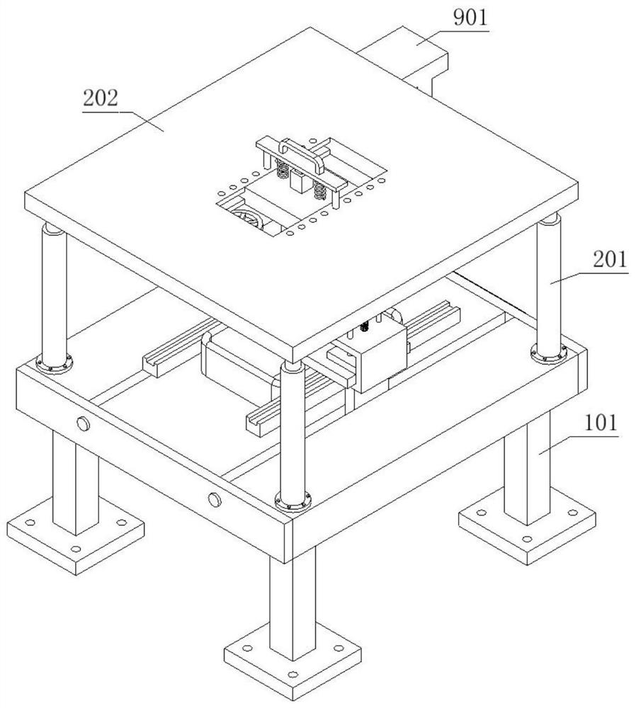
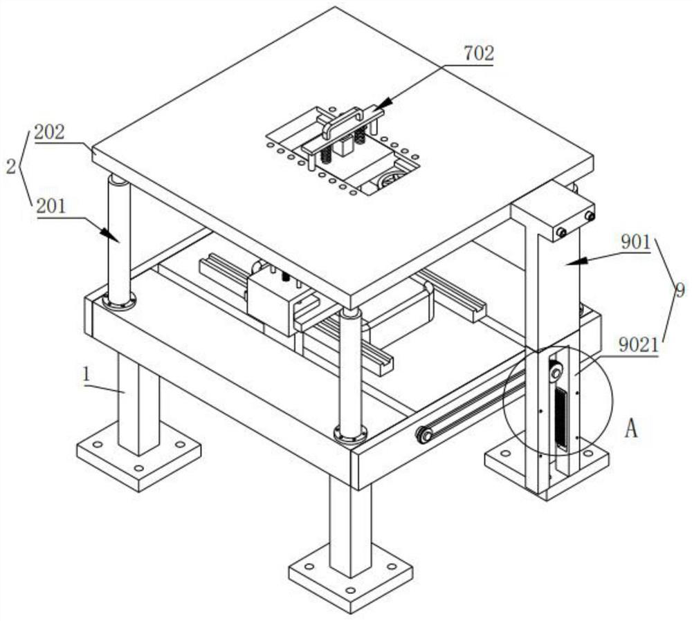
[0035] The present invention provides a stamping device for metal substrate production, including an installation mechanism 1;

[0036] A lifting part 2 is installed on the top of the installation mechanism 1;

[0037] There are two groups of clamping parts 3, and the two groups of clamping parts 3 are symmetrically installed on the top of the installation mechanism 1, and a lower mold 4 is arranged between the two groups of clamping parts 3, and the two groups of clamping parts A fixing part 5 is installed inside the tightening part 3;

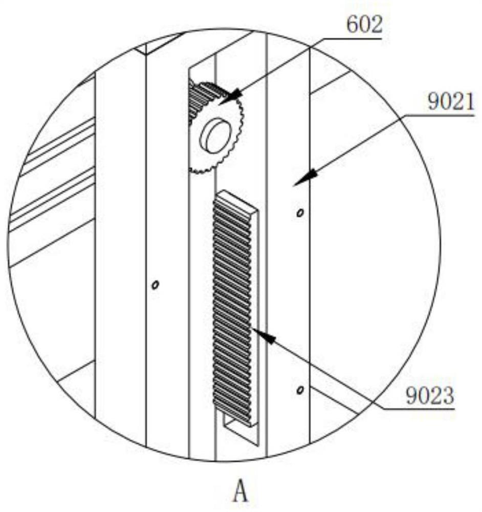
[0038] The connecting part 6, the connecting part 6 is installed inside the installation mechanism 1;

[0039] The stamping part 7, the stamping part 7 is installed on the lifting part 2;

[0040] The collecting part 8, the collecting part 8 is installed on the bottom of the installation mechanism 1;

[0041] The moving part 9 is installed on the right side of the lifting part 2 ...

Embodiment 2

[0075] In the actual production and processing of metal substrates, there is a deviation in the thickness of each metal substrate, requiring the operator to manually rotate the locking member 304 to clamp the metal substrate, and the operator cannot accurately judge the clamping force on the metal substrate, there is a certain Potential safety hazards reduce production efficiency at the same time. To improve the above-mentioned problems, control is carried out according to the method described in this embodiment.

[0076] The installation mechanism 1 includes a base 101 and a control unit. A chute is opened on the upper surface of the base 101, and a fixing hole 102 is provided in the chute; the installation mechanism 1 is fixedly connected with the installation plate 202 through an electric push rod 201; A clamping part 3 is provided, and the clamping part 3 includes a slider 301. One end of the slider 301 is slidably connected to the chute, and the other end is fixedly connec...

Embodiment 3

[0080] Since the length of the bump on the stamping head 703 is fixed and the depth of the opening of the lower mold 4 is fixed, when stamping a thicker metal substrate, the stamping head 703 cannot penetrate the lower mold 4 so that there are foreign objects in the hole of the lower mold 4. It will hinder the next stamping, resulting in the failure of normal production of the metal substrate. In order to improve the above problems, control is performed according to the method described in this embodiment.

[0081] The bottom of the installation mechanism 1 is provided with a collection part 8, the collection part 8 includes: a support base 801, the support base 801 is fixedly connected with the installation frame 101, the installation frame 101 is slidingly connected with the storage groove 802, and the storage box 802 and the support base 801 are fixed Springs are installed, and the front and rear sides of the storage box 802 are fixedly equipped with connecting rods 803 and ...


PUM


Abstract

The invention provides a stamping device for metal base plate production. The stamping device comprises a mounting mechanism, two sets of clamping parts, a connecting part, a collecting part, a stamping part and a moving part; a lifting part is mounted at the top of the mounting mechanism; the two sets of clamping parts are symmetrically mounted at the top of the mounting mechanism, a lower mold is arranged between the two sets of clamping parts, and fixing parts are mounted in the two sets of clamping parts; the connecting part is mounted in the mounting mechanism; the stamping part is mounted on the lifting part; the collecting part is mounted at the bottom of the mounting mechanism; and the moving part is mounted on the right side of the lifting part. Two limiting blocks are slidably connected into two guide grooves, so that when two fixing columns are located in two fixing holes in the middle, the top of a storage box is tightly attached to the bottom of the lower mold, splashing of crushed materials after stamping is avoided, on the one hand, the sanitary environment of a working area is improved, and the cleaning time of workers is shortened; and on the other hand, the workers are prevented from being hurt by the splashed crushed materials.

Description

technical field [0001] The invention belongs to the technical field of stamping of metal substrates, and more specifically relates to a stamping device for the production of metal substrates. Background technique [0002] Metal substrate is a kind of metal circuit board material, which belongs to electronic general components. It is composed of heat-conducting insulating layer, metal plate and metal foil. Substrates often need to be punched to meet different needs during processing, specifically: splayed holes, hexagonal holes, punched plates, long holes, square holes, round holes, punched mesh, triangular holes and so on. [0003] For example, the patent application number: CN202011118970.3 discloses a stamping processing device for punching metal plates, including a fixing seat, a connecting cylinder, a supporting leg, a shock absorbing mechanism, a placing plate, a blanking frame, a fixing frame, a reinforcement Plate, hydraulic cylinder, moving mechanism and clamping an...

Claims


Application Information

Patent Timeline
Patent Type & Authority Applications(China)
IPC IPC(8): B21D28/26B21D28/04B21D28/34B21D43/20B21D55/00B21C51/00
CPCB21D28/26B21D28/04B21D28/34B21D43/20B21D55/00B21C51/00
Inventor 赵艳菊
Owner 深圳市建宏达照明电路有限公司
Why Eureka
Try Eureka