Oil cooler with reinforcing ribs

An oil cooler and reinforcing rib technology, applied in the direction of gear lubrication/cooling, belt/chain/gear, transmission parts, etc., can solve the problems of insufficient welding strength, difficult process, unfavorable requirements for automobile energy saving, etc. Processing time, reducing the overall weight, and ensuring the effect of heat transfer

Pending Publication Date: 2021-10-29
沈平
View PDF0 Cites 0 Cited by
  • Summary
  • Abstract
  • Description
  • Claims
  • Application Information

AI Technical Summary

Problems solved by technology

However, the cooling area of ​​the above-mentioned pipe body is limited, and a better lubricating oil cooling effect cannot be achieved.
[0004] Therefore, the original water-cooled structure has gradually developed and transitioned to the air-cooled stacked oil cooler, but the air-cooled stacked structure has more parts and solder joints, the process is difficult, and the failure rate is high. Cost and The weight of a single piece is relatively high
At the same time, there are many parts, difficult process assembly, and large flow resistance and wind resistance, which is not conducive to the market's requirements for automobile energy saving
When assembling the oil cooler tube body into an oil cooler, due to the unreasonable structural design, the welding strength is insufficient, so that the working pressure that the oil cooling tube body can withstand during work is small, and the pressure intensity at the inlet and outlet ends of the oil cooling tube body is also low. Weak, can not meet the requirements of use

Method used


Image

  • Oil cooler with reinforcing ribs
  • Oil cooler with reinforcing ribs
  • Oil cooler with reinforcing ribs

Examples


Embodiment 1

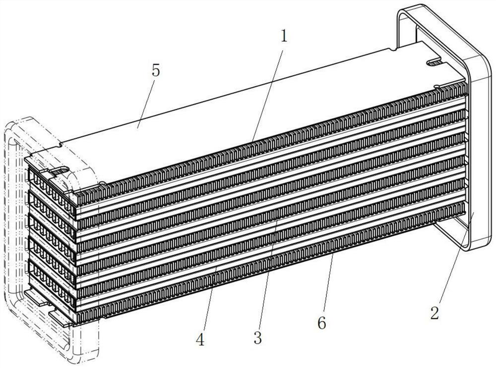
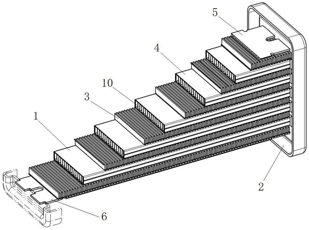
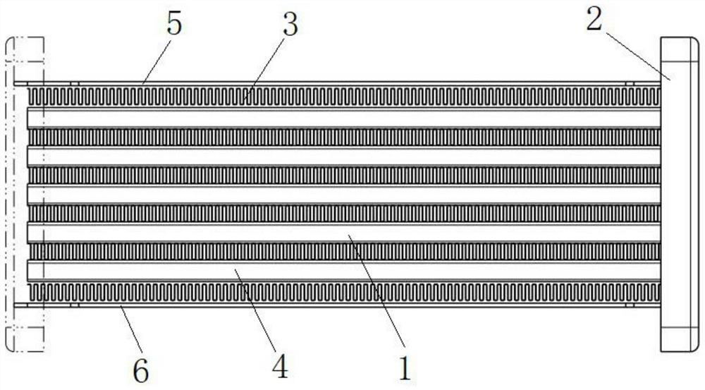
[0050] Such as Figure 1-9 As shown, the oil cooler with ribs in this embodiment includes a body, the body includes a core 1 and a main board 2 welded to both ends of the core 1; the core 1 includes six heat dissipation strips 3 and Five oil cooler tubes 4, heat dissipation belts 3 and oil cooler tubes 4 are alternately overlapped, the top of the uppermost heat dissipation belt 3 on the core 1 is welded with an upper guard plate 5, and the bottom of the lowermost heat dissipation belt 3 is welded with a lower guard Plate 6; the main board 2 at the left end of the body is provided with oil inlet holes 7 corresponding to the number and positions of the oil cooler tubes 4, and the main board 2 at the right end of the body is provided with oil outlet holes 8 corresponding to the number and positions of the oil cooler tubes 4 .

[0051] The oil cooler tube 4 includes a first tube body 9 and inner fins 10; the first tube body 9 is bent from a whole piece of alloy material, the thic...

Embodiment 2

[0056] Such as Figure 7-10 The difference between this embodiment and Embodiment 1 is that the main body of the oil cooler in this embodiment also includes a mounting base 18, and the top of the mounting base 18 is welded to the bottom plate of the main board 2 and the bottom of the lower guard plate 6 respectively; the mounting base 18 A positioning hole 19 is provided on the top, and a protruding positioning ring 20 is provided at the bottom of the mounting base 18 and around the bottom of the positioning hole 19 .

[0057] Working principle: After the oil cooler of this embodiment is positioned and installed through the positioning hole 19 and the positioning ring 20 on the installation base 18, the lubricating oil to be cooled enters the oil cooler tube 4 from the oil inlet hole 7, and flows from the inner fin 10 The spoiler groove 17 passes through, and the spoiler groove 17 reduces the flow velocity of the lubricating oil, and the lubricating oil exchanges heat with the...

Embodiment 3

[0059] Such as Figure 11 As shown, the difference between this embodiment and Embodiment 1 is that this embodiment uses a second pipe body 21 instead of the first pipe body 9, and the second pipe body 21 is bent into a flat shape from a whole piece of alloy material. Shaped tube body, its thickness, wall thickness and width are consistent with the first tube body 9. A reinforcement piece 22 with a thickness of 0.5 mm is provided on the inner walls of both sides of the second pipe body 21 . The working principle of this embodiment is consistent with that of Embodiment 1.


PUM


Abstract

The invention discloses an oil cooler with reinforcing ribs. The oil cooler comprises a body. The body comprises a core and main plates welded to two ends of the core. The core comprises heat dissipation belts and oil cooler pipes which are alternately overlapped, the number of the heat dissipation belts is one more than that of the oil cooler pipes, an upper protection plate is welded to the top of the heat dissipation belt in the uppermost layer of the core, and a lower protection plate is welded to the bottom of the heat dissipation belt in the lowermost layer of the core; oil inlet holes corresponding to oil cooler pipes in number and position are formed in a main plate at one end of the body, and oil outlet holes corresponding to the oil cooler pipes in number and position are formed in a main plate at the other end of the body. The oil cooler is light in weight, high in strength, capable of bearing a large working pressure, high in assembly speed and convenient and fast to mount. The qualified rate of finished products is high, and raw material consumables can be saved by about 20% under the condition that performance requirements are met. The sealing performance is high, the flow resistance and wind resistance are small, the cooling efficiency is high, and the automobile capacity loss is reduced. The oil cooler has wide popularization and application values and improves the market competitiveness of enterprises.

Description

technical field [0001] The invention relates to the technical field of automobile radiator components, in particular to an oil cooler with reinforcing ribs. Background technique [0002] When the car is running, the temperature of the lubricating oil contained in the gearbox will continue to rise due to the transmission of power. If the temperature of the lubricating oil is too high, it may cause the lubricating oil to boil and lose its lubricating effect, thus making the gears easy to wear. How to ensure The lubricating oil temperature in the gearbox will not be too high, which becomes a very important issue. In the existing structural configuration of automobiles, oil cooler tubes are provided to cool lubricating oil and ensure that the oil temperature is within the normal working range. [0003] The automobile oil cooler in the prior art includes an oil cooler tube body, the oil cooler tube body has inner and outer double-layer tube walls, the tube ends of the inner and ...

Claims


Application Information

Patent Timeline
Patent Type & Authority Applications(China)
IPC IPC(8): F16H57/04
CPCF16H57/0413F16H57/0417
Inventor 沈平
Owner 沈平
Why Eureka
Try Eureka