Container type crushing device convenient to maintain
A crushing device and container-type technology, applied in the field of material crushing, can solve the problems of limited space, time-consuming and labor-consuming, and small operating space, and achieve the effects of small shape, reduced transportation cycle, and reduced transportation costs
- Summary
- Abstract
- Description
- Claims
- Application Information
AI Technical Summary
Problems solved by technology
Method used
Image
Examples
Embodiment 1
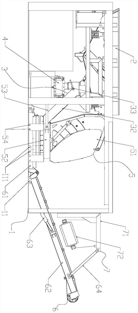
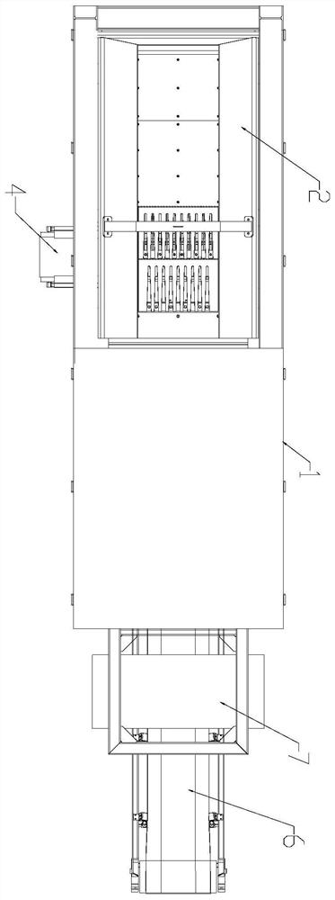
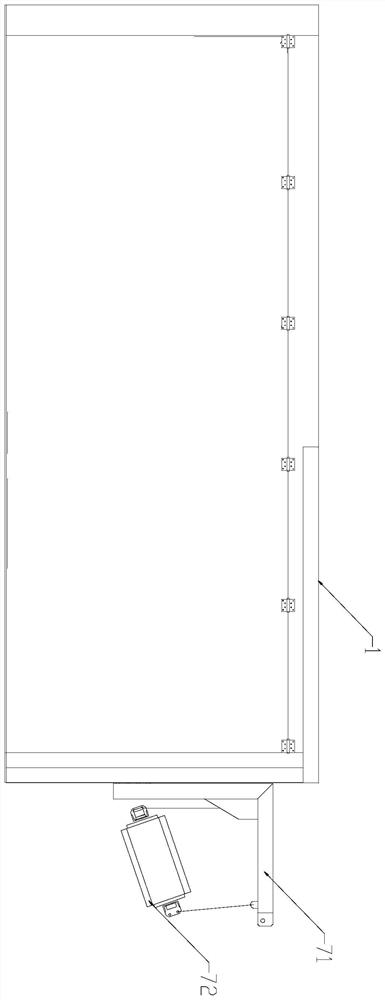
[0027] Such as Figure 1-7 A container-type crushing device that is easy to maintain is shown, including a container 1, a feed pre-screening unit 2, a material distribution unit 3, a soil removal unit 4, a crushing unit 5, a discharge unit 6, and an iron removal unit 7. The iron remover unit 7 is installed on the outer surface of the right side of the container 1, and the iron remover unit 7 is located above the discharge unit 6, and the iron remover unit 7 includes an L-shaped bracket 71, an L-shaped bracket installed on the L-shaped bracket 71 Permanent magnetic iron remover 72, the permanent magnetic iron remover 72 is connected to the horizontal part of the L-shaped bracket 71, the vertical part of the L-shaped bracket 71 is connected to the container 1, in order to reuse the metal in the material, the iron remover The unit 7 separates the metal and non-metal components in the material on the discharge unit 6, and has a good recovery effect on the metal material in the mat...
Embodiment 2
[0035] Such as figure 1 , 4 As shown, the right side in the container 1 is provided with a positioning block 11, and the positioning hole 11 is provided with a positioning hole 111. The positioning block 11 is used to limit the base 52, so that the crusher 51 can be fixed at the maintenance position, which is convenient for workers to adjust the position. Crusher 52 for maintenance.
[0036] The crushing unit 5 includes a crusher 51, a base 52, and a pushing device 53. The crusher 51 is installed on the top of the base 52, and the pushing device 53 is used to push the crusher 51 to an inspection position. The crusher 51 is hinged to the base 52 , the pushing device 53 includes a first hydraulic cylinder 531 and a second hydraulic cylinder 532, the first hydraulic cylinder 531 is used to push the base 52 to slide to the positioning block 11, and the second hydraulic cylinder 532 is used to turn the crusher 51 to the left 60°~180°, which is convenient for the operator to maint...
Embodiment 3
[0040] As a preferred solution, the rotating shaft 33 has a Z-shaped structure, a disc 36 is arranged between the rotating shaft 33 and the cylinder 31, and the disc 36 is provided with a fifth through hole for installing the rotating shaft 33, The sixth through hole 361 (such as Figure 8 shown), the sixth through hole 361 is connected with a U-shaped pin, and the U-shaped pin includes two pin arms, and the sixth through hole is not less than 2, preferably 2 or 4, and the sixth through hole Six through holes 361 are distributed on both sides along the center line of the disk 36, and the sixth through holes 361 are arranged symmetrically. The inner side of the disk 36 is inclined downward. When the material distribution plate 35 is required to be in the middle, rotate the rotating shaft 33 so that the material distribution plate 35 is in a vertical state, and insert the U-shaped latch obliquely downward into the sixth through hole 361, while the two pin arms of the U-shaped l...
PUM
 Abstract
Description
Claims
Application Information
 - R&D Engineer
- R&D Manager
- IP Professional
- Industry Leading Data Capabilities
- Powerful AI technology
- Patent DNA Extraction
Browse by: Latest US Patents, China's latest patents, Technical Efficacy Thesaurus, Application Domain, Technology Topic, Popular Technical Reports.
© 2024 PatSnap. All rights reserved.Legal|Privacy policy|Modern Slavery Act Transparency Statement|Sitemap|About US| Contact US: help@patsnap.com


