

Parallel rail type intelligent robot composite bending forming machining method and device
An intelligent robot and bending forming technology, applied in the field of pipe forming and processing, can solve the problems of the difficulty of hollow pipe fittings, the inability to guarantee the dimensional accuracy and forming quality of forming components, increase the complexity of the process flow, the production cost and cycle, etc., and achieve the optimization of the forming process. , to achieve automatic intelligent operation, avoid the effect of interference
- Summary
- Abstract
- Description
- Claims
- Application Information
AI Technical Summary
Problems solved by technology
Method used
Image

Examples
Embodiment 1
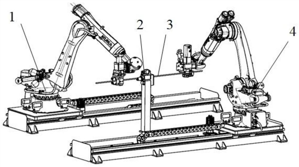
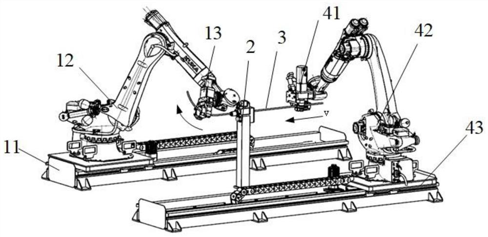
[0048] image 3 Schematic diagram of the free bending forming stage of free bending / twisting composite forming, Figure 4 Schematic diagram of bending stage after torsion in free bending / twisting composite forming. The free bending forming device 13 and the bending forming device 41 are installed at the ends of the industrial robots 12 and 42 respectively, and the industrial robots 12 and 42 are installed on the ground rails. The two robots are arranged in parallel and can move along the ground rails 11 and 43; The holding guiding device 2 is between the two robots. The free bending forming system 1 and the bending forming system 4 are respectively located on both sides of the external clamping and guiding device 2, and both include a robot motion control system and a bending mold control system. The robot controls the position and posture of the free bending forming device 13 to realize space bending forming with different curvatures, and is guided by the external clamping ...
Embodiment 2
[0059] Figure 5 Schematic diagram of the free bending forming stage of free bending / bending compound forming, Figure 6 Schematic diagram of the bending forming stage of free-bending / bending composite forming. The free bending forming device 13 and the bending forming device 41 are installed at the ends of the industrial robots 12 and 42 respectively, and the industrial robots 12 and 42 are installed on the ground rails 11 and 43. The two robots are arranged in parallel and can be carried out along the ground rails 11 and 43. Movement; the external holding guide 2 is between the two robots. During the bending and forming process of pipe fittings, the free bending forming system 1 and the bending forming system 4 perform bending and forming sequentially according to the characteristics of each bending part. For the small bending radius section with a straight section, the winding forming process is used; Segment / no straight segment with large relative bending radius segment / ...
PUM
 Abstract
Description
Claims
Application Information