Welding device applied to aluminum die-casting automobile engine pipe fitting
A technology for automobile engines and welding devices, applied in auxiliary devices, welding equipment, welding equipment, etc., can solve the problems of low processing efficiency and high production costs, and achieve the effects of cost saving, simple operation, and avoiding the movement of the rotating circle
- Summary
- Abstract
- Description
- Claims
- Application Information
AI Technical Summary
Problems solved by technology
Method used
Image

Examples
Embodiment 1
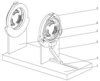
[0035] see Figure 1-3 , the present invention provides a technical solution: a welding device applied to aluminum die-casting automobile engine pipe fittings, specifically comprising:
[0036] Base 1, the two ends of the top of the base 1 are respectively provided with a fixed bracket 2 and a sliding bracket 3, the bottom of the fixed bracket 2 is fixedly connected with the top of the base 1, the top of the base 1 is provided with a slideway 4, and the bottom of the sliding bracket 3 extends to the inside of the slideway 4 And slidingly connected with the inner wall of the slideway;
[0037] A support plate 5, one side of the support plate 5 is fixedly connected with a clamping device 6, the support plate 5 is provided with two groups and symmetrically distributed on the fixed bracket 2 and the sliding bracket 3;
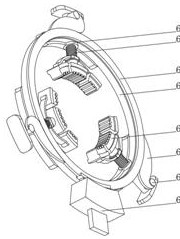
[0038] The clamping device 6 includes:
[0039] Fixed slideway 61, the top of the fixed slideway 61 runs through and is fixedly connected with a sliding sleeve 6...
Embodiment 2
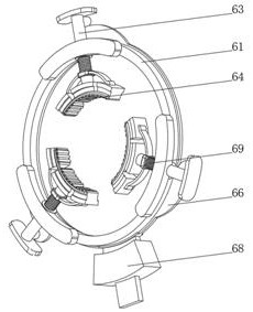
[0045] see Figure 1-4 On the basis of Embodiment 1, the present invention provides a technical solution: the buckle device 68 includes a fixing seat 681, the inner wall of the fixing seat 681 is slidably connected with an arc-shaped chuck 682, and the bottom of the arc-shaped chuck 682 is fixedly connected with a pull rod 683, The end of the pull rod 683 away from the arc-shaped chuck 682 runs through the fixed seat 681 and extends to the outside of the fixed seat 681. The part of the pull rod 683 located inside the fixed seat 681 is provided with a tensioning spring 684, and the side of the fixed seat 681 is fixedly connected with the support plate 5. The top of the arc-shaped chuck 682 is provided with a friction pad and is slidably connected with the rotating ring 65, and is provided with a buckle device 68. When the rotating ring 65 needs to be rotated, pull the pull rod 683, and the pull rod 683 drives the arc-shaped chuck 682 to push the side of the rotating ring 65. , ...
Embodiment 3
[0047] see Figure 1-5 , on the basis of Embodiment 1 and Embodiment 2, the present invention provides a technical solution: the clamping device 64 includes a fixed plate 641, the bottom of the fixed plate 641 is fixedly connected with a clamping top post 642, and both sides of the fixed plate 641 are fixedly connected There is an arc spring 643, the bottom of the clamping top column 642 is fixedly connected with a main chuck 644, and the end of the arc spring 643 away from the fixed plate 641 is fixedly connected with a sub-chuck 645, and the inner walls of the main chuck 644 and the sub-chuck 645 are both An installation groove 646 is opened, and the inner wall of the installation groove 646 is slidingly connected with a friction strip 647. The top of the fixing plate 641 is fixedly connected with the bottom of the ejector rod 63. One end of the installation groove 646 is provided with a bottom cover, and a clamping device 64 is arranged inside the clamping device 64. There ...
PUM
 Abstract
Description
Claims
Application Information
 - R&D
- Intellectual Property
- Life Sciences
- Materials
- Tech Scout
- Unparalleled Data Quality
- Higher Quality Content
- 60% Fewer Hallucinations
Browse by: Latest US Patents, China's latest patents, Technical Efficacy Thesaurus, Application Domain, Technology Topic, Popular Technical Reports.
© 2025 PatSnap. All rights reserved.Legal|Privacy policy|Modern Slavery Act Transparency Statement|Sitemap|About US| Contact US: help@patsnap.com