Portable rust removal equipment for H-shaped steel welding bead in steel structure parking equipment
A technology for parking equipment and H-beams, applied in metal processing equipment, grinding/polishing equipment, manufacturing tools, etc., can solve problems such as corrosion of steel structures, increase work efficiency of H-beam weld bead operations, improper protection measures, etc. The effect of manual labor intensity, convenient rust removal, and improved work efficiency
- Summary
- Abstract
- Description
- Claims
- Application Information
AI Technical Summary
Problems solved by technology
Method used
Image
Examples
Embodiment 1
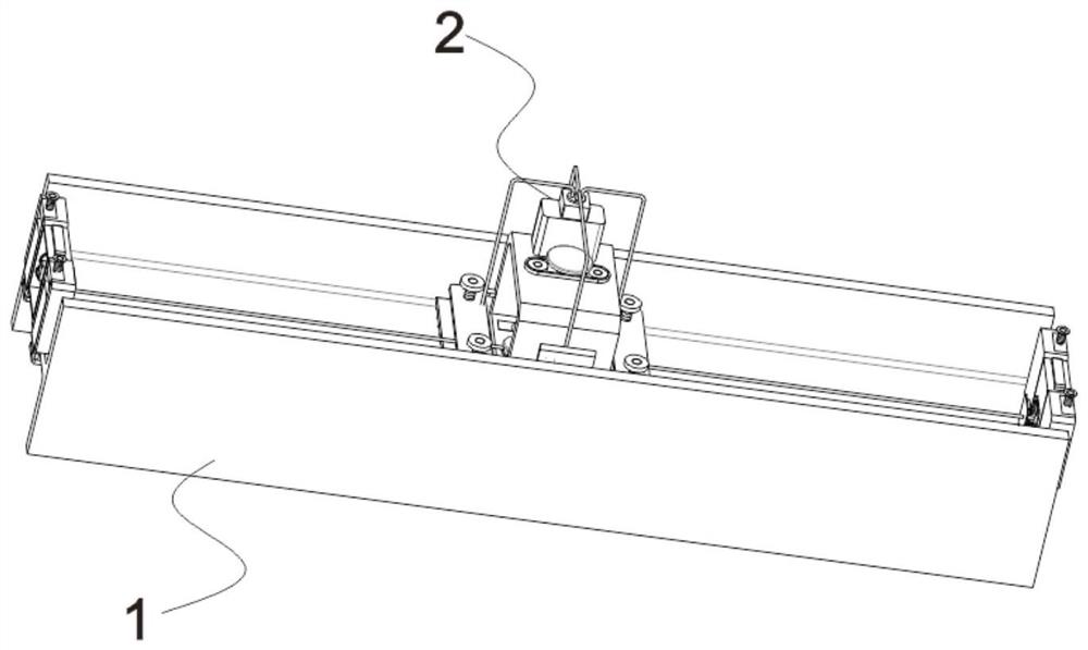
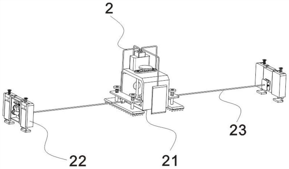
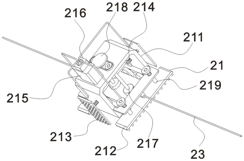
[0024] see Figure 1-5 , the present invention provides portable derusting equipment for H-shaped steel welding bead in steel structure parking equipment (the electrical components in the present invention are all provided with power by the storage battery in the walking seat 211, and will not be described in detail here), including,
[0025] H-shaped steel welding bead main body 1, H-shaped steel welding bead main body 1 is widely used in this field, as attached figure 1 , which includes a top notch and a bottom notch, and the position of the derusting equipment is described as being installed at the top notch;
[0026] Rust removal and maintenance equipment 2 includes a walking part 21 arranged on the top of the H-shaped steel welding bead main body 1, and the walking part 21 moves in the notch of the H-shaped steel welding bead main body 1. Of course, the rust removal and maintenance equipment 2 can also be installed on the H-shaped steel welding bead main body 1. The side...
Embodiment 2
[0030] see image 3 , the left and right sides of the inner wall of the bottom of the walking seat 211 are fixed with coil shells 217, and coil shells 217 are provided with coiling parts, the coil coils are rolls, and the opposite sides of the left and right coil shells 217 are provided with rope inlets. The opposite ends of the left and right traction ropes 23 respectively enter the coil shell 217 and are wound on the outer wall of the winding piece. The winding piece can be rewound or unrolled. The roll shell 217 is rotated inside for rewinding or unwinding, and the top of the rod moves through the top of the walking seat 211. The top of the walking seat 211 and the position between the two groups of rods are vertically rotated and provided with an auxiliary rod. The auxiliary rod adopts the end bearing The rotation is arranged on the top of the walking seat 211, and the auxiliary rod and the two groups of rod bodies are connected through a sprocket transmission group. The ...
Embodiment 3
[0034] see Figure 4-5 , the traction member 22 includes two sets of front and rear symmetrical limiting members 221, a driving member 222 is fixed between the two groups of limiting members 221, and a mounting plate is fixed on the side of the driving member 222 close to the walking seat 211, and the mounting plate is close to the walking seat One side front and rear ends of 211 are all provided with spring one 223, and the other end of spring one 223 is fixed with movable plate 225, when winding traction rope 23, make moving block 226 contact movable plate 225, when continuing to roll again, make mobile Block 226 drives movable plate 225 to move, and then makes touch block contact button module 224, movable plate 225 is provided with touch block away from the side of walking seat 211, and the side of mounting plate near walking seat 211 is fixed with touch block. The matching button module 224, the button module 224 is widely used in this field, including a touch open module...
PUM
 Abstract
Description
Claims
Application Information
 - R&D
- Intellectual Property
- Life Sciences
- Materials
- Tech Scout
- Unparalleled Data Quality
- Higher Quality Content
- 60% Fewer Hallucinations
Browse by: Latest US Patents, China's latest patents, Technical Efficacy Thesaurus, Application Domain, Technology Topic, Popular Technical Reports.
© 2025 PatSnap. All rights reserved.Legal|Privacy policy|Modern Slavery Act Transparency Statement|Sitemap|About US| Contact US: help@patsnap.com


