
Cascade absorption type system

An absorption type and absorber technology, which is applied in the field of cascade absorption type systems, can solve the problems of high energy consumption, low integration, and large floor space, so as to reduce energy consumption, reduce power, and reduce floor space. Effect

Active Publication Date: 2021-11-02
ANHUI WATERPOWER ENERGY SAVING TECH
View PDF13 Cites 0 Cited by
  • Summary
  • Abstract
  • Description
  • Claims
  • Application Information

AI Technical Summary

Problems solved by technology

[0004] The public document with the application number CN201310521246.9 proposes an ammonia and lithium bromide integrated absorption refrigeration device and method driven by heat medium water. Through the integrated absorption refrigeration technology of ammonia and lithium bromide, the use of heat medium water at 90-120°C to produce The purpose of the secondary refrigerant at -30-19°C is to save heat, improve refrigeration efficiency, and reduce refrigeration costs compared with conventional steam-driven ammonia and lithium bromide absorption refrigeration processes. However, the device is composed of multiple devices, integrated Low cost, large footprint, high energy consumption

Method used


Image

  • Cascade absorption type system
  • Cascade absorption type system

Examples


Embodiment 1

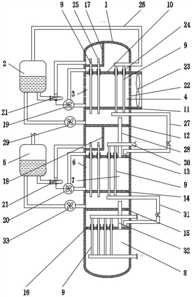
[0026] Such as figure 1 As shown, in this embodiment, the shell side of the primary absorber 3 and the primary condenser 4 use circulating water, the shell side of the secondary absorber 6 and the secondary condenser 7 use liquid refrigerant, and the secondary evaporator The shell side of 8 uses liquid refrigerant, the tube side of heat exchange tube 9 of primary absorber 3 and secondary absorber 6 uses lean solution, and the tube side of heat exchange tube 9 of primary condenser 4 and secondary condenser 7 runs through Gaseous refrigerant, the heat exchange tube 9 tube side of the secondary evaporator 8 carries the refrigerant.

[0027] Specifically, the heat exchange tubes 9 of the primary absorber 3, the primary condenser 4, the secondary absorber 6, the secondary condenser 7, and the secondary evaporator 8 are all equipped with liquid distribution tubes outside the tubes near the corresponding partitions at the upper end. 24, the circulating water inlet of the first-stage...

Embodiment 2

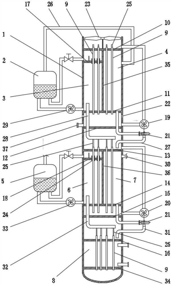
[0032] Such as figure 2 As shown, in this embodiment, the heat exchange tubes 9 of the primary absorber 3 and the primary condenser 4 run through circulating water, and the heat exchange tubes 9 of the secondary absorber 6 and the secondary condenser 7 run through the tubes Circulating liquid refrigerant, the heat exchange tube 9 of the secondary evaporator 8 passes the refrigerant, the shell side of the primary absorber 3 and the secondary absorber 6 passes the lean solution, the primary condenser 4, and the secondary condenser 7 The shell side of the secondary evaporator 8 uses the refrigerant, and the shell side of the secondary evaporator 8 uses the secondary refrigerant.

[0033]Specifically, the eleventh partition 35 is vertically located between the first partition 10 and the second partition 11, and is used to separate the heat exchange tube 9 area of ​​the primary absorber 3 and the primary condenser 4, and the twelfth partition The plate 36 is vertically located be...


PUM


Abstract

The invention relates to a cascade absorption type system, and belongs to the technical field of absorption type refrigeration. The system comprises a shell, a first-stage generator, a first-stage absorber, a first-stage condenser, a second-stage generator, a second-stage absorber, a second-stage condenser and a second-stage evaporator. The first-stage absorber, the first-stage condenser, the second-stage generator, the second-stage absorber, the second-stage condenser and the second-stage evaporator are sequentially located in the shell from top to bottom, the first-stage absorber and the first-stage condenser are distributed side by side, and the second-stage absorber and the second-stage condenser are distributed side by side. Heat exchange tubes in the first-stage absorber, the first-stage condenser, the second-stage absorber, the second-stage condenser and the second-stage evaporator are all vertically arranged. Multiple heat exchangers in the cascade absorption type system are integrated into one heat exchange equipment, so that the whole arrangement is compact, the occupied area is reduced, power of a circulating pump is greatly reduced through the evaporative condensers and the absorbers, and energy consumption of the system is reduced.

Description

technical field [0001] The invention belongs to the technical field of absorption refrigeration, and in particular relates to a cascade absorption system. Background technique [0002] Traditional compression refrigeration is a conversion process of electrical energy. The compressor draws the low-pressure and low-temperature refrigerant gas produced in the evaporator, such as Freon, into the cylinder, and after being compressed, it becomes a gas with a higher pressure and temperature and is discharged into the condenser. It is condensed into a liquid, and then enters the evaporator through a pressure regulating valve to throttle and reduce the pressure. At this time, the low-pressure refrigerant gas vaporizes and absorbs the heat in the evaporator to cool down. The compression process requires a large amount of electric energy. [0003] Waste heat refrigeration is a technology that uses gas or waste gas, waste liquid in the production process, and the heat discharged by som...

Claims


Application Information

Patent Timeline
IPC IPC(8): F25B7/00F25B35/02F25B39/04
CPCF25B7/00F25B35/02F25B39/04Y02A30/27Y02B30/62
Inventor 陈何根祝令辉
Owner ANHUI WATERPOWER ENERGY SAVING TECH
Learn More