
Vehicle target pose detection method, device and storage medium based on tight boundary constraints network

A detection method and target technology, applied in neural learning methods, biological neural network models, instruments, etc., can solve problems such as greater influence on network detection results, increased experiment complexity, and more calculations, so as to improve monitoring efficiency and improve Detection accuracy, overcoming the effect of low detection accuracy

Active Publication Date: 2021-12-07
HUNAN UNIV
View PDF9 Cites 0 Cited by
  • Summary
  • Abstract
  • Description
  • Claims
  • Application Information

AI Technical Summary

Problems solved by technology

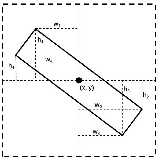
CHEN C et al. adopted a one-stage detection framework and designed a multi-scale adaptive correction network to detect targets in any direction and return the direction angle. The designed model uses five parameters to describe the rotation frame information, where is the target center point coordinates , , are the length and width, and the azimuth is a total of 5 parameters to describe the information of the target rotation frame, where the target azimuth is defined as the angle at which the horizontal axis rotates counterclockwise to intersect with the target rotation frame, and the range is (-90°, 0° ], which is different from the traditional one-stage detection model. The rotating anchor frame is used to solve the problem of target azimuth estimation, but the setting of hyperparameters such as anchor frame angle and aspect ratio needs to be determined through more comparison and ablation experiments. And the above hyperparameters have a great influence on the network detection results, so if you want the network effect to reach the ideal state, the determination of the above hyperparameters will increase a lot of calculation and increase the complexity of the experiment

Method used


Image

  • Vehicle target pose detection method, device and storage medium based on tight boundary constraints network
  • Vehicle target pose detection method, device and storage medium based on tight boundary constraints network
  • Vehicle target pose detection method, device and storage medium based on tight boundary constraints network

Examples


Embodiment Construction

[0035] The following will clearly and completely describe the technical solutions in the embodiments of the present invention in conjunction with the embodiments of the present invention. Apparently, the described embodiments are only some of the embodiments of the present invention, not all of them. Based on the embodiments of the present invention, all other embodiments obtained by persons of ordinary skill in the art without making creative efforts belong to the protection scope of the present invention.

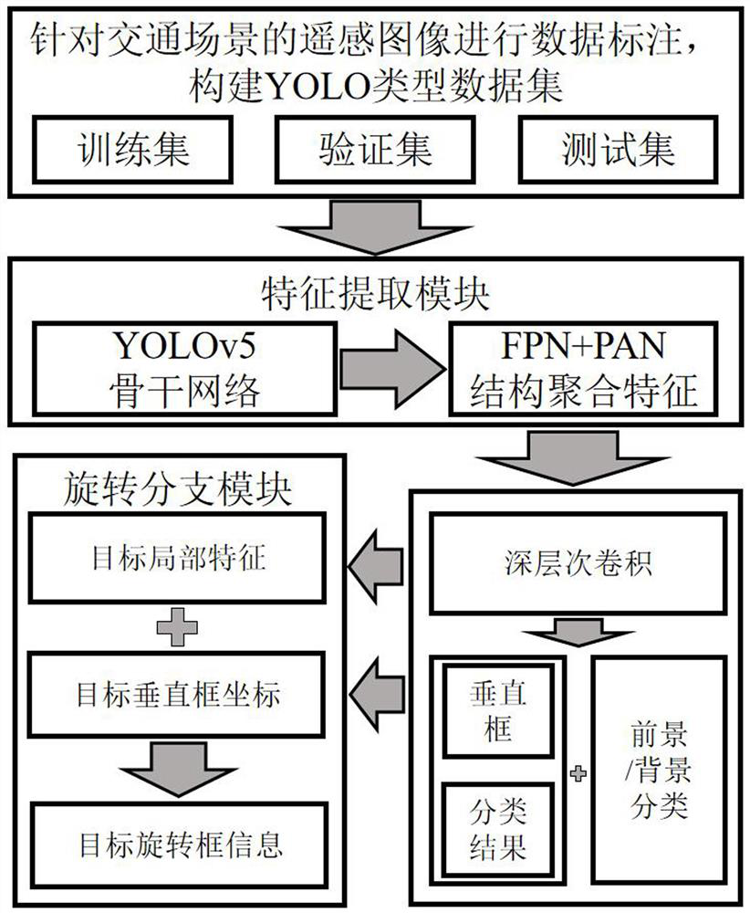
[0036] see figure 1 As shown, the present invention provides a vehicle target pose detection method based on a tight boundary constraint network, the method comprising the following steps:

[0037] Step 1. Data preprocessing: Carry out data annotation on the vehicle targets in the remote sensing image of the traffic scene to obtain the image data, and use the image data to construct a YOLO type data set, which includes a training set, a test set and a verification set;

...


PUM


Abstract

The invention discloses a vehicle target pose detection method, device and storage medium based on a tight boundary constraint network, and relates to remote sensing image target detection technology, considering that in the actual road traffic scene application environment, vertical frames are used to detect vehicle density That is, target detection is easily affected by factors such as complex road environment and high vehicle density, resulting in false detection, missed detection, etc., and using a rotating rectangular frame for vehicle detection can improve this situation. Therefore, a new addition is made to the network structure of YOLOv5. The rotation branch converts multi-scale features and original detection results into rotating frame detection results with angle information, and redefines the multi-task loss function based on the original loss function and rotation branch to improve detection accuracy while meeting real-time requirements.

Description

technical field [0001] The present invention relates to the technical field of end-to-end anchor-free image target search based on deep learning, in particular to a vehicle target pose detection method, device and storage medium based on a tight boundary constraint network. Background technique [0002] With the vigorous development of the Internet of Things, deep learning, and traffic monitoring technology, the concept of intelligent transportation has gradually entered the public's field of vision. At the same time, as more and more companies begin to enter the market of unmanned vehicles, intelligent transportation has also become a new development. direction. The essence of smart transportation is not a simple smart car or smart monitoring, but a system, a closed-loop system composed of multiple elements such as vehicles, roads, people, cloud, and monitoring. And information such as roads and pedestrians fed back by roadside facilities, complete intelligent calculation ...

Claims


Application Information

Patent Timeline
Patent Type & Authority Patents(China)
IPC IPC(8): G06K9/00G06K9/46G06K9/62G06N3/04G06N3/08
CPCG06N3/04G06N3/08G06F18/214G06F18/253
Inventor 李庆鹏王子安李智勇方乐缘李亚萍
Owner HUNAN UNIV
Learn More