Stirring and mixing equipment for thin film raw materials
A technology of stirring and mixing raw materials, which is applied in the field of stirring and mixing equipment for film raw materials, can solve the problem that metal particles with large density particles cannot be effectively removed, and achieve the effect of stable structure, stable stirring and good effect
- Summary
- Abstract
- Description
- Claims
- Application Information
AI Technical Summary
Problems solved by technology
Method used
Image
Examples
Embodiment 1
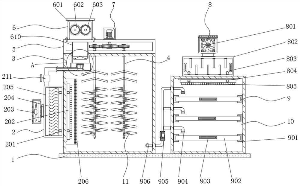
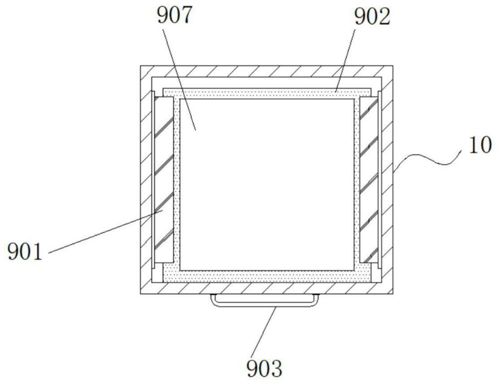
[0042] Example 1: See Figure 1-7 , a stirring and mixing device for film raw materials, comprising a bottom plate 1, one side of the top of the bottom plate 1 is fixedly connected with a cylinder 3, the other side of the top of the bottom plate 1 is fixedly connected with a box 10, and the top of the cylinder 3 is fixedly connected with a fixed Seat 5, one side of the top of the fixed seat 5 is provided with a crushing mechanism 6, one side of the cylinder 3 is provided with a heating mechanism 2, the inside of the box body 10 is provided with a feeding mechanism 9, and the top of the box body 10 is provided with a cooling mechanism 8 , the interior of the cylinder 3 is provided with a stirring mechanism;
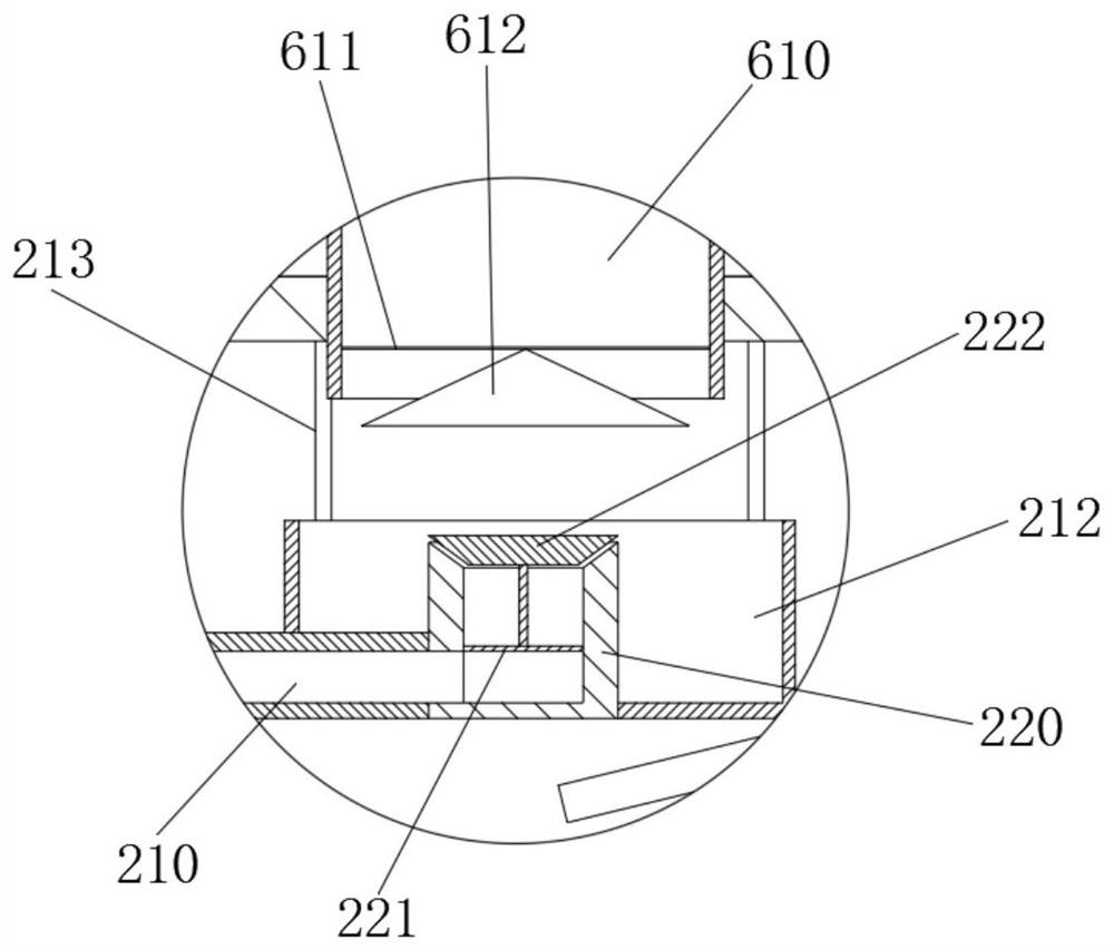
[0043] The pulverizing mechanism is connected with the cylinder body through the feed pipe 610, and a separation mechanism is installed in the cylinder body at the feed pipe 610, and the separation mechanism is connected with the heating mechanism through the air guide pip...
Embodiment 2
[0048] Embodiment 2: The heating mechanism 2 is composed of a heat ventilation pipe 201, a first distribution pipe 202, a first blower fan 203, a heating wire 204, a connecting seat 205, a connecting cover 206 and a ventilation hole 207, and the connecting seat 205 is fixedly connected to the base plate 1 On one side, the inside of the connecting seat 205 is provided with a heating wire 204. The model of the heating wire 204 can be 0Cr25Al5. The other side of the connecting seat 205 is fixedly connected with a first fan 203 through a connecting pipe. For XG-3, one side inside the connection seat 205 is fixedly connected with the heat ventilation pipe 201, and the other side of the heat ventilation pipe 201 penetrates the inside of the cylinder 3 and extends to the inside of the first distribution pipe 202, the first branch The piping 202 is fixedly connected to one side inside the cylinder body 3, the other side of the first distribution pipe 202 is fixedly connected to a venti...
Embodiment 3
[0051] Embodiment 3: The crushing mechanism 6 is composed of a placement seat 601, a first crushing wheel 602, a second crushing wheel 603, a driving wheel 604, a servo motor 605, a driven wheel 606 and a belt 607, and the placement seat 601 is fixedly connected to the top of the fixed seat 5 One side of the placement seat 601 is provided with a first crushing wheel 602, and the other side of the placement seat 601 is provided with a second crushing wheel 603, and one end of the first crushing wheel 602 is connected with the driven wheel 606 through a connecting piece One end of the second pulverizing wheel 603 is connected to the driving wheel 604 through a connecting piece, a belt 607 is arranged outside between the driven wheel 606 and the driving wheel 604, and the other end of the driving wheel 604 is connected to the output end of the servo motor 605 through a shaft connector connection, the model of the servo motor 605 can be ASD-A2;
[0052] The diameter of driven whee...
PUM
 Abstract
Description
Claims
Application Information
 - R&D
- Intellectual Property
- Life Sciences
- Materials
- Tech Scout
- Unparalleled Data Quality
- Higher Quality Content
- 60% Fewer Hallucinations
Browse by: Latest US Patents, China's latest patents, Technical Efficacy Thesaurus, Application Domain, Technology Topic, Popular Technical Reports.
© 2025 PatSnap. All rights reserved.Legal|Privacy policy|Modern Slavery Act Transparency Statement|Sitemap|About US| Contact US: help@patsnap.com


