Vehicle-mounted autonomous charging platform for unmanned aerial vehicle

A self-charging and unmanned aerial vehicle technology, applied in the field of unmanned aerial vehicles, can solve the problems of high positioning accuracy, short endurance of unmanned aerial vehicles, poor adaptability and flexibility, etc., so as to avoid complex mechanisms and fast mobile deployment , Improve the effect of robustness and success rate

Active Publication Date: 2021-11-05
BEIHANG UNIV
View PDF7 Cites 6 Cited by
  • Summary
  • Abstract
  • Description
  • Claims
  • Application Information

AI Technical Summary

Problems solved by technology

[0002] In recent years, drones have been used more and more widely in production and life, such as pesticide spraying, logistics delivery, and military reconnaissance; however, drones generally have the problem of short battery life, so the development of autonomous charging technology for drones very necessary
[0003] Existing autonomous charging devices can be divided into wireless and contact types; the mechanical structure required for wireless charging is simple, but the charging efficiency is low; the contact charging method is efficient, but requires a more complex mechanical structure and accurate positioning Sexually demanding
[0004] At the same time, most of the existing UAV charging devices charge for fixed base stations. Such base stations are often large in size, and at the same time, due to the location of the base station, a large amount of electric energy is wasted in the process of the UAV going to and from the base station. Therefore, the adaptability and flexibility are relatively high. Difference

Method used


Image

  • Vehicle-mounted autonomous charging platform for unmanned aerial vehicle
  • Vehicle-mounted autonomous charging platform for unmanned aerial vehicle
  • Vehicle-mounted autonomous charging platform for unmanned aerial vehicle

Examples


Embodiment Construction

[0042] The present invention will be further described in detail with reference to the accompanying drawings and implementation examples.

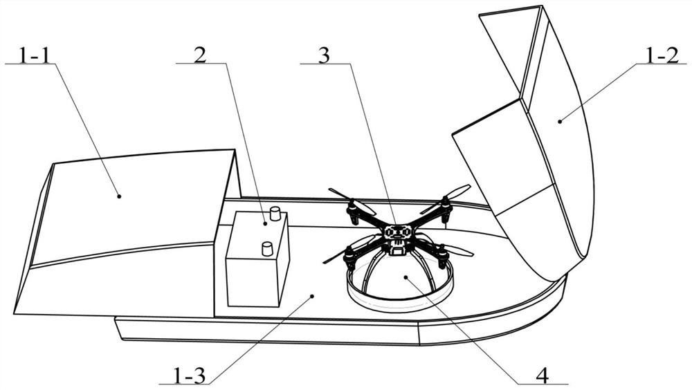
[0043] The invention is a vehicle-mounted unmanned aerial vehicle autonomous charging platform, such as figure 1 As shown, it includes roof hangar 1, take-off and landing boss 4, charging interface device 5 and quadrotor UAV 3;

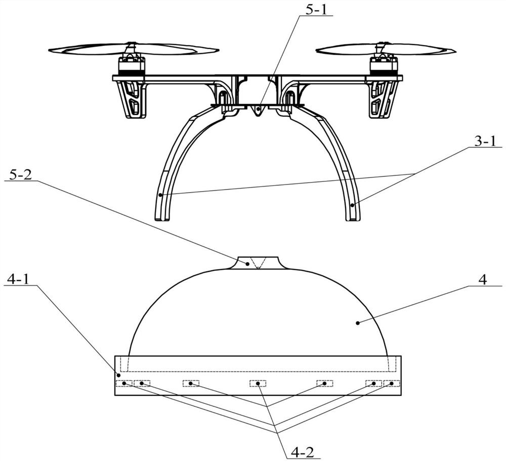
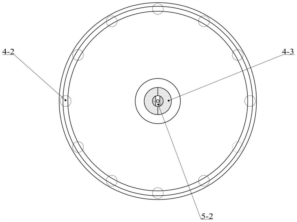
[0044] The roof hangar 1 is equipped with a take-off and landing boss 4 and a battery 2, and the battery 2 provides power for the take-off and landing boss 4; 1 and the female connector 5-2, and the shape and outline of the male and female connectors are completely matched, so that the two can be in close contact, ensuring the reliability of the quadrotor UAV 3 docking on the take-off and landing boss 4 for autonomous charging. Electrical and data lines are arranged in the roof hangar floor 1-3, and are equipped with corresponding interfaces to connect with the vehicle.

[0045]The roof hangar 1 is based on the ...


PUM


Abstract

The invention discloses a vehicle-mounted autonomous charging platform for an unmanned aerial vehicle, belonging to the technical field of unmanned aerial vehicles. The vehicle-mounted autonomous charging platform comprises a roof hangar, a take-off and landing boss and a quad-rotor unmanned aerial vehicle which are mounted in the roof hangar, and a charging interface device matched with the unmanned aerial vehicle and the take-off and landing boss, wherein an electromagnet array is arranged at the bottom of the take-off and landing boss and used for tightly adsorbing landing legs of the unmanned aerial vehicle; and the unmanned aerial vehicle comprises a controller, the controller is divided into a position controller and an attitude controller, and position stabilization and attitude stabilization of the unmanned aerial vehicle are respectively controlled by calculating resultant external force and resultant external torque generated by the unmanned aerial vehicle. The autonomous charging platform is further provided with a circuit system; when the unmanned aerial vehicle is charged, the controller measures voltage every 0.1 s, on-off information of a charging circuit is indirectly obtained, and if the charging circuit is disconnected, the controller controls the unmanned aerial vehicle to adjust posture again until the charging circuit is closed again to continue charging. According to the invention, a requirement on the pose accuracy of the unmanned aerial vehicle is reduced, and the robustness and success rate of autonomous landing are improved.

Description

technical field [0001] The invention belongs to the technical field of unmanned aerial vehicles, in particular to a vehicle-mounted unmanned aerial vehicle autonomous charging platform. Background technique [0002] In recent years, drones have been used more and more widely in production and life, such as pesticide spraying, logistics delivery, and military reconnaissance; however, drones generally have the problem of short battery life, so the development of autonomous charging technology for drones It is very necessary. [0003] Existing autonomous charging devices can be divided into wireless and contact types; the mechanical structure required for wireless charging is simple, but the charging efficiency is low; the contact charging method is efficient, but requires a more complex mechanical structure and accurate positioning Sexual requirements are high. [0004] At the same time, most of the existing UAV charging devices charge for fixed base stations. Such base stat...

Claims


Application Information

Patent Timeline
Patent Type & Authority Applications(China)
IPC IPC(8): B64F1/00B60L53/53B60L53/30B60L53/16B60L53/60B64C27/08G05D1/10
CPCB64F1/007B60L53/53B60L53/30B60L53/16B60L53/60B64C27/08G05D1/106B60L2200/10B64U30/20B64U50/19B64U80/86B64U10/10Y02T10/70Y02T10/7072Y02T90/12Y02T90/14
Inventor 张毅超张真睿汪菊南尹一凡诸兵
Owner BEIHANG UNIV
Why Eureka
Try Eureka