A Lean Oil Direct Injection Low Pollution Combustion Chamber Using Bubble Atomizing Nozzles

A technology for atomizing nozzles and combustion chambers, which is applied in combustion chambers, continuous combustion chambers, combustion methods, etc., to achieve the effects of reducing the risk of coking, easy assembly, and reducing pollution emissions

Active Publication Date: 2018-10-19
BEIHANG UNIV
View PDF14 Cites 1 Cited by
  • Summary
  • Abstract
  • Description
  • Claims
  • Application Information

AI Technical Summary

Problems solved by technology

[0023] The technical problem to be solved by the present invention is: to overcome the deficiencies of the prior art, and to use lean fuel direct injection combustion technology to provide a lean fuel direct injection low-pollution combustion chamber using bubble atomizing nozzles, and the fuel passes through multiple bubble atomizing nozzles Atomized into extremely fine and uniform liquid mist, directly sprayed into the combustion chamber for combustion

Method used


Image

  • A Lean Oil Direct Injection Low Pollution Combustion Chamber Using Bubble Atomizing Nozzles
  • A Lean Oil Direct Injection Low Pollution Combustion Chamber Using Bubble Atomizing Nozzles
  • A Lean Oil Direct Injection Low Pollution Combustion Chamber Using Bubble Atomizing Nozzles

Examples


Embodiment Construction

[0042] The present invention will be further described below in conjunction with the accompanying drawings and specific embodiments.

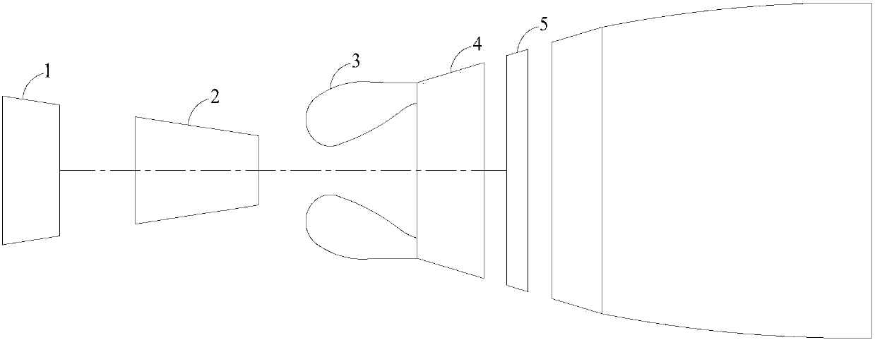
[0043] figure 1 It is a schematic diagram of the engine structure, including a low-pressure compressor 1, a high-pressure compressor 2, a combustion chamber 3, a high-pressure turbine 4 and a low-pressure turbine 5. When the engine is working, the air is compressed by the low-pressure compressor 1 and enters the high-pressure compressor 2. The high-pressure air then enters the combustion chamber 3 to burn with fuel. The high-temperature and high-pressure gas formed after combustion enters the high-pressure turbine 4 and low-pressure turbine 5, and passes through the turbine. Work is done to drive the high-pressure compressor 2 and the low-pressure compressor 1 respectively.

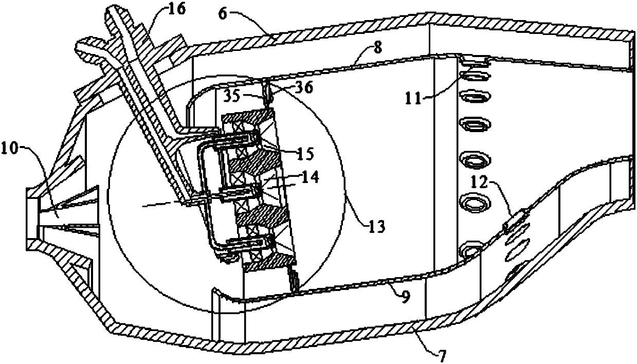
[0044] Such as figure 2 As shown, the head of the combustion chamber adopts a central hierarchical structure, the pre-combustion stage is at the center, and the main co...


PUM


Abstract

The invention discloses a lean direct injection low-emission combustor adopting effervescent atomizers. A single-ring cavity structure is adopted in the combustor. The lean direct injection low-emission combustor comprises a diffuser, a combustor outer case, a combustor inner case, a flame tube outer wall, a flame tube inner wall and combustor heads. Fuel oil is atomized into liquid mist which is extremely thin and extremely uniform through the multiple effervescent atomizers, and the liquid mist is directly injected into the combustor for combustion. A staged combustion structure is adopted in the combustor. A sinking design is adopted in a center precombustion stage, and the flame stabilizing function is played; and the flame is stabilized depending on the precombustion stage for primary combustion stages of the periphery of the precombustion stage, and the primary combustion stages start to work according to the needs of the working conditions. The lean direct injection technology is adopted in the low-emission combustor, the fuel oil is injected into the combustor through the multiple effervescent atomizers, and the spatial distribution uniformity of the fuel oil is increased; and the fuel oil is injected through the special effervescent atomizers, and therefore the fuel oil has the good atomizing quality, fuel oil atomizing and mixing are facilitated, distribution uniformity of the fuel oil is further increased, and the combustor has the great potential in reducing pollution emission.

Description

technical field [0001] The invention relates to the technical field of aviation gas turbines, in particular to a fuel-lean direct-injection low-pollution combustor using bubble atomizing nozzles. The combustor adopts a staged combustion mode, with a pre-combustion stage at the center, and adopts diffusion combustion and premixed combustion. Combination method, while ensuring the stable combustion of the combustion chamber, reduces pollution emissions under small working conditions; the main combustion stage is on the periphery of the pre-combustion stage, and adopts the pre-mixed pre-evaporative combustion method, which is mainly used to reduce the pollution emissions under large working conditions. Pollution emissions, thereby reducing the pollution emissions of the entire landing and take-off (LTO) cycle of the aero-engine. Background technique [0002] The basic performance and structural distribution of modern aero-engine combustors have reached a fairly high level, but ...

Claims


Application Information

Patent Timeline
Patent Type & Authority Patents(China)
IPC IPC(8): F23R3/28F23R3/20
CPCF23R3/20F23R3/28
Inventor 张弛王波李宇航林宇震
Owner BEIHANG UNIV
Why Eureka
Try Eureka