Earth shoulder paver and construction method thereof
A technology of soil road shoulder and paver, applied in the direction of road, road, road repair, etc., can solve problems such as low work efficiency, and achieve the effect of improving construction efficiency, improving equipment quality, and ensuring construction quality
- Summary
- Abstract
- Description
- Claims
- Application Information
AI Technical Summary
Problems solved by technology
Method used
Image
Examples
Embodiment 1
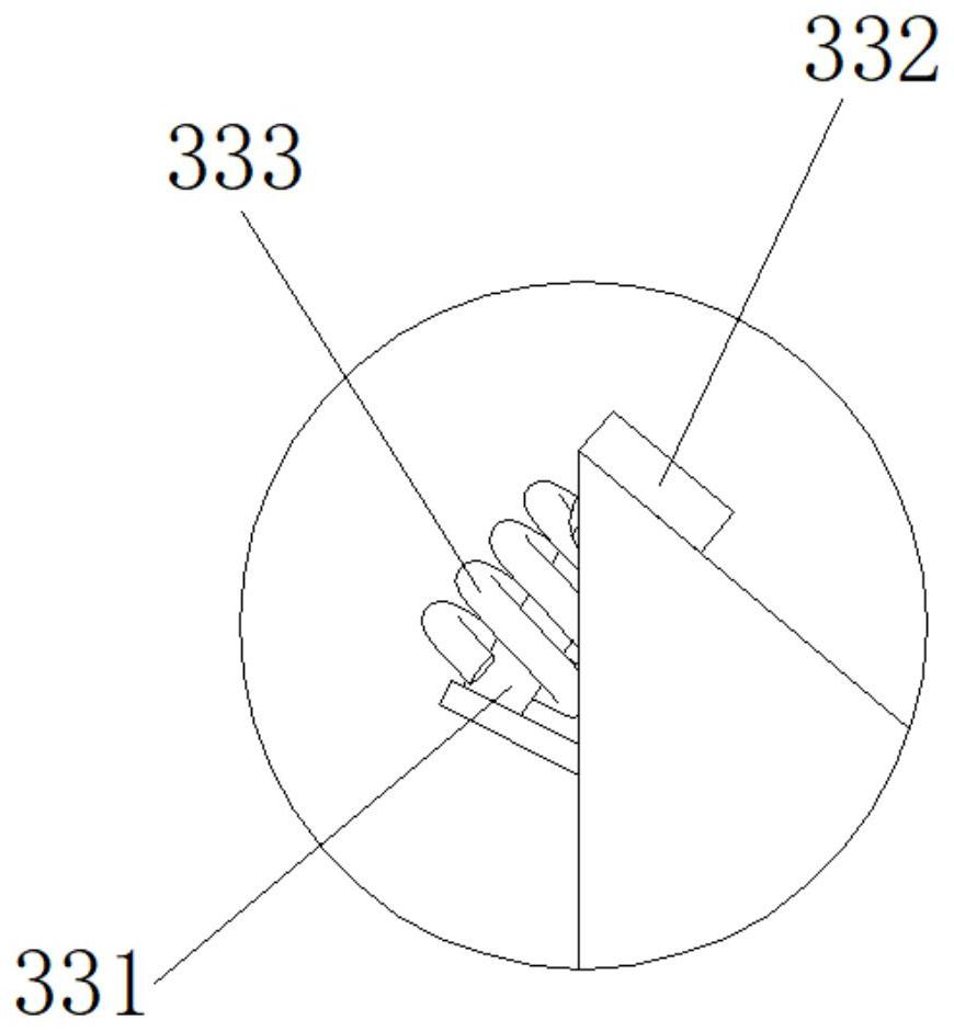
[0030] refer to figure 1 and figure 2 , a soil road shoulder paver, comprising a feed bin 1, a top left end of the feed bin 1 is provided with a feed inlet 11, and the bottom right end of the feed bin 1 is provided with a discharge port 12, the discharge port 12 is rectangular, and the discharge port 12 The length direction is the same as the axis direction of the silo 1. A screw shaft is installed inside the silo 1. One end of the screw shaft is rotatably connected with the left end face of the silo 1, and the other end of the screw shaft is rotatably connected with the right end face of the silo 1. , drive motor is installed on the left end face of feed bin 1, and drive motor is connected with screw shaft to drive screw shaft to rotate, and the right end of feed bin 1 that soil material is pushed from the left end of feed bin 1 falls from discharge opening 12 when screw shaft rotates.
[0031] The rear of the side wall of the silo 1 is fixedly connected with a first connec...
Embodiment 2
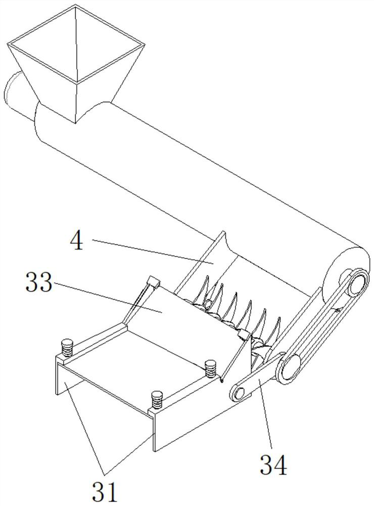
[0038] refer to image 3 , different from Embodiment 1, the first connecting plate 4 is connected with the compacting mechanism through the second connecting plate 34, the top of the second connecting plate 34 is rotationally connected with the end of the first connecting plate 4, and the second connecting plate 34 The bottom end is rotatably connected to the outside of the inclined section of the side plate 31, so that the height of the compaction mechanism can be adjusted. It can be extended or replaced at the bottom of the side plate 31 with a higher height. At this time, the height of the compaction mechanism increases to achieve different heights. Work function on highly soiled shoulders.
[0039] A crushing roller 41 can also be arranged between the first connecting plates 4, the setting direction of the crushing roller 41 and the screw shaft is the same, the two ends of the crushing roller 41 are rotationally connected with the first connecting plate 4, and the right en...
Embodiment 3
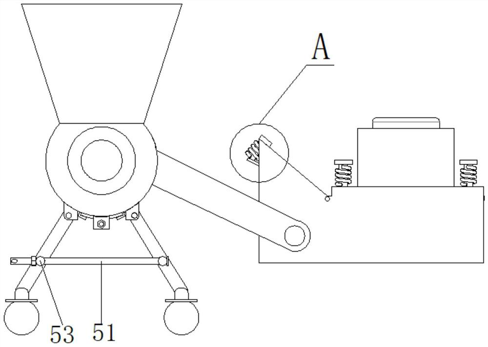
[0041] refer to Figure 4 , on the basis of Embodiment 2, a lifting device and a walking wheel 6 are installed at the bottom of the silo 1, and the walking wheel 6 is connected with the silo 1 through the lifting device, so that the silo 1 can slide forward under the action of the walking wheel 6 At the same time, the height of the bin 1 can be adjusted through the height adjustment of the lifting device, so that the height of the compaction mechanism can be adjusted through the fixed first connecting plate 4 .
[0042] The quantity of elevating mechanism is several, is preferably 2, and elevating mechanism can be selected as the mechanism with telescoping function, such as cylinder, oil cylinder or ball screw etc., and the structure of elevating mechanism is preferably, and elevating device comprises connecting rod 51, the first Support leg 521 and the second support leg 522, the first support leg 521 and the second support leg 522 are rotated and installed with the bottom of...
PUM
 Abstract
Description
Claims
Application Information
 - R&D
- Intellectual Property
- Life Sciences
- Materials
- Tech Scout
- Unparalleled Data Quality
- Higher Quality Content
- 60% Fewer Hallucinations
Browse by: Latest US Patents, China's latest patents, Technical Efficacy Thesaurus, Application Domain, Technology Topic, Popular Technical Reports.
© 2025 PatSnap. All rights reserved.Legal|Privacy policy|Modern Slavery Act Transparency Statement|Sitemap|About US| Contact US: help@patsnap.com


