Guide rail type closed-loop single-phase miniature current transformer
What is Al technical title?
Al technical title is built by PatSnap Al team. It summarizes the technical point description of the patent document.
A current transformer and rail type technology, applied in the field of transformers, can solve the problems of small scope of application, low practicability, inconvenient adjustment of the upper and lower heights of transformers, etc., to achieve a wide range of applications, improve work efficiency, and save work time. Effect
Inactive Publication Date: 2021-11-05
周红翠
View PDF0 Cites 0 Cited by
Summary
Abstract
Description
Claims
Application Information
AI Technical Summary
This helps you quickly interpret patents by identifying the three key elements:
Problems solved by technology
Method used
Benefits of technology
Problems solved by technology
[0004] The purpose of the present invention is to provide a rail-type closed-loop single-phase miniature current transformer, to solve the problem that the rail-type closed-loop single-phase miniature current transformer in the prior art proposed in the above-mentioned background technology is not convenient for the staff to carry out the transformer up and down. The adjustment of the height leads to the problem that its application range is small and the practicability is not high
Method used
Image
Click on the blue label to locate the original text in one second.
Reading with bidirectional positioning of images and text.
Examples
Embodiment Construction
[0030] The following will clearly and completely describe the technical solutions in the embodiments of the present invention with reference to the accompanying drawings in the embodiments of the present invention. Obviously, the described embodiments are only some, not all, embodiments of the present invention. Based on the embodiments of the present invention, all other embodiments obtained by persons of ordinary skill in the art without making creative efforts belong to the protection scope of the present invention.
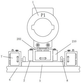
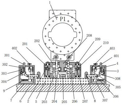
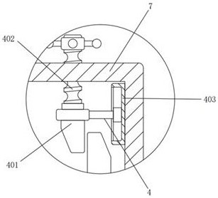
[0031] see Figure 1-6 , the present invention provides a technical solution: a rail-type closed-loop single-phase miniature current transformer, including a base plate 5, a transformer 1 is arranged above the base plate 5, a rod body 8 is welded on the top side of the base plate 5, and one end of the rod body 8 Grooves are processed, the bottom of the bottom plate 5 is bonded with a long plate 6, the top side of the long plate 6 is welded with a shell 3 7, a ...
PUM
Abstract
The invention discloses a guide rail type closed-loop single-phase miniature current transformer. The current transformer comprises a bottom plate, a mutual inductor is arranged above the bottom plate, a lifting structure is arranged above the bottom plate, the lifting structure comprises a first sliding block, a first shell, a first vertical plate, a vertical rod, a first spring, a curved rod, a round block, a second vertical plate, a first threaded rod and a secondshell, the bottom of the first shell is fixedly connected with the top of the bottom plate, and a vertical rod is in clearance fit with the inner wall of one side of the top of the first shell. According to the guide rail type closed-loop single-phase miniature current transformer, through cooperation of the transformer, a bottom plate, a long plate, a third shell, a rod body, a first sliding rod and the lifting structure, a first threaded rod is rotated, the first threaded rod drives a first sliding block to move downwards, the first sliding block drives a round block to move downwards, the round block drives a bent lever to rotate, the bent lever drives the second vertical plate to move upwards, and the second vertical plate drives the transformer to move upwards, so that a worker can conveniently adjust the vertical height of the transformer, the application range is wide, and practicability is high.
Description
technical field [0001] The invention relates to the technical field of transformers, in particular to a rail-type closed-loop single-phase miniature current transformer. Background technique [0002] Transformer, also known as instrument transformer, is a general term for current transformer and voltage transformer. It can change high voltage into low voltage and large current into small current for measuring or protection system. Its function is mainly to convert high voltage or large current into standard low voltage (100V) or standard small current (5A) in proportion or 1A, both refer to the rated value), in order to realize the standardization and miniaturization of measuring instruments, protection equipment and automatic control equipment. At the same time, the transformer can also be used to isolate the high-voltage system to ensure the safety of people and equipment. [0003] The guide-rail type closed-loop single-phase miniature current transformer in the prior ar...
Claims
Application Information
Patent Timeline
Application Date:The date an application was filed.
Publication Date:The date a patent or application was officially published.
First Publication Date:The earliest publication date of a patent with the same application number.
Issue Date:Publication date of the patent grant document.
PCT Entry Date:The Entry date of PCT National Phase.
Estimated Expiry Date:The statutory expiry date of a patent right according to the Patent Law, and it is the longest term of protection that the patent right can achieve without the termination of the patent right due to other reasons(Term extension factor has been taken into account ).
Invalid Date:Actual expiry date is based on effective date or publication date of legal transaction data of invalid patent.