An industrial robot electric control box

A technology of industrial robots and electric control boxes, which is applied in the field of robots, can solve the problems of increasing the difficulty of device cleaning, reducing the service life of devices, and damage to electronic components, so as to achieve the effects of improving convenience, prolonging service life, and reducing the difficulty of cleaning

Active Publication Date: 2021-12-14
思岚机器人(南通)有限公司
View PDF13 Cites 1 Cited by
  • Summary
  • Abstract
  • Description
  • Claims
  • Application Information

AI Technical Summary

Problems solved by technology

[0006] Aiming at the deficiencies of the prior art, the present invention provides an electric control box for an industrial robot, which solves the problem of easy accumulation of dust in the interior of the electric control cabinet after long-term use. Because the internal connection position is fixed, it increases the difficulty of cleaning the inside of the device. Electronic components are prone to damage, which reduces the service life of the device

Method used


Image

  • An industrial robot electric control box
  • An industrial robot electric control box
  • An industrial robot electric control box

Examples


Embodiment 1

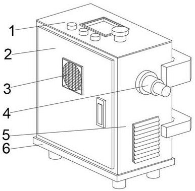
[0041] see Figure 1-Figure 6 , the present invention provides a technical solution: an industrial robot electric control box, including a stable base 6, a placement device 5 is fixedly connected to the top of the stable base 6, and a box door 2 is provided on the front top of the placement device 5, and the box door 2 A cooling fan 3 is arranged in the middle of the top, and the back of the cooling fan 3 penetrates the box door 2 and extends to the inside of the box door 2. A telescopic connecting rod 4 is arranged at the middle of the top of the right outer wall of the placing device 5, and the top of the placing device 5 is fixed. A control panel 1 is connected;

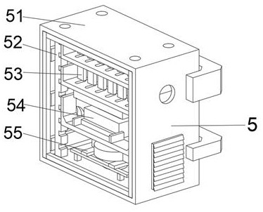
[0042] The placing device 5 includes a device main body 51 , a protective mechanism 55 is provided in the middle position of the bottom of the inner cavity of the device main body 51 , a guide mechanism 54 is provided in the middle position of the top of the protective mechanism 55 , and a connecting frame 52 is s...

Embodiment 2

[0048] see Figure 1-Figure 6 , on the basis of the first embodiment, the present invention provides a technical solution: a method of using an industrial robot electric control box, step 1: the equipment is installed and fixed, and the box door 2 is connected with the placement device 5, so that The right side of the box door 2 can be opened and closed while driving the cooling fan 3 to make it move, connecting the stable base 6 with the placing device 5, and connecting the placing device 5 with the power supply;

[0049] Step 2: The connecting frame 52 is vertically lifted and lowered by the guide mechanism 54, so that the placing plate 53 connected to it moves on the connecting frame 52, so as to The ventilation plate connected on the main body 51 can speed up the circulation of the internal air when it is opened;

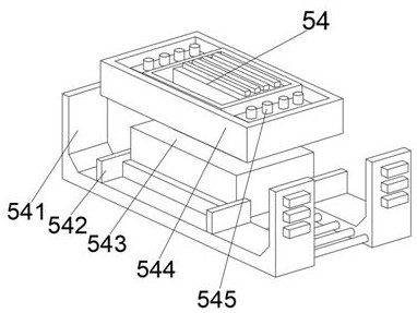
[0050] Step 3: Use the slider of the lift carrier 541 to drive the connection mechanism 543 fixedly connected with the positioning connection plate 542 to move...


PUM


Abstract

The invention discloses an electric control box for an industrial robot, which comprises a stable base, a placement device is fixedly connected to the top of the stable base, a box door is arranged on the front top of the placement device, and a box door is arranged in the middle of the top of the box door. A cooling fan, the back of the cooling fan runs through the box door and extends to the inside of the box door, a telescopic connecting rod is arranged in the middle of the top of the right outer wall of the placement device, and a control panel is fixedly connected to the top of the placement device. The invention relates to the field of robotics. The electric control box of the industrial robot effectively increases the cleaning area inside the device, which can reduce the difficulty of cleaning the inside of the device, and the ventilating plate on the main body of the device can be opened and closed automatically, thereby keeping the internal temperature of the device constant, avoiding the Electronic components are damaged by internal high temperature and cause short circuit, which is beneficial to prolong the service life of the device, and thus improves the convenience of internal circuit connection of the device.

Description

technical field [0001] The invention relates to the technical field of robots, in particular to an industrial robot electric control box. Background technique [0002] An industrial robot is a multi-joint manipulator or a multi-degree-of-freedom robot for the industrial field. An industrial robot is a machine device that performs work automatically. It is a machine that realizes various functions by its own power and control capabilities. It can accept human commands. It can also run according to pre-arranged programs. Modern industrial robots can also act according to the principles and programs formulated by artificial intelligence technology. Because industrial robots need to be used in a wide range of places, they can often be used in multiple places. [0003] According to Chinese Patent No. CN111385988A, an electric control cabinet for industrial robots can be used together with a placing plate, a sponge pad, a shock-absorbing spring, a rubber pad, a bearing seat, a scr...

Claims


Application Information

Patent Timeline
Patent Type & Authority Patents(China)
IPC IPC(8): H05K5/00H05K5/02H05K7/14H05K7/20B01D53/26
CPCH05K5/0213H05K5/0217H05K5/0004H05K7/14H05K7/20009B01D53/26
Inventor 黎龙飞
Owner 思岚机器人(南通)有限公司
Why Eureka
Try Eureka