Visual biological membrane culture reactor and in-situ observation method

A technology for cultivating reactors and biofilms, applied in bioreactor/fermenter combinations, specific-purpose bioreactor/fermenter, chemical instruments and methods, etc., can solve the inconvenience of in-situ sampling and the inability to realize real-time visual observation and other issues, to achieve the effect of buffer protection

Pending Publication Date: 2021-11-09
ZHEJIANG GONGSHANG UNIVERSITY
View PDF8 Cites 0 Cited by
  • Summary
  • Abstract
  • Description
  • Claims
  • Application Information

AI Technical Summary

Problems solved by technology

[0006] The invention provides a visual reactor to a biofilm reactor, which overcomes the bottlenecks that the traditional biofilm reactor cannot realize real-time visual observation and the inconvenient in-situ sampling, in-situ staining, and in-situ confocal observation and detection of existing visual reactors. Mechanistic studies during biofilm reactions provide strong support

Method used


Image

  • Visual biological membrane culture reactor and in-situ observation method
  • Visual biological membrane culture reactor and in-situ observation method
  • Visual biological membrane culture reactor and in-situ observation method

Examples


Embodiment 1

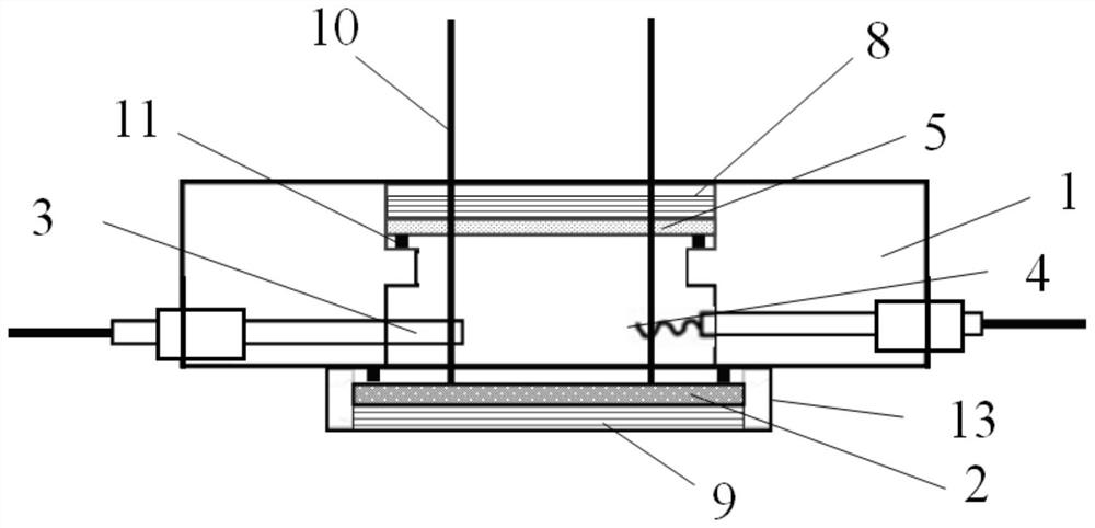
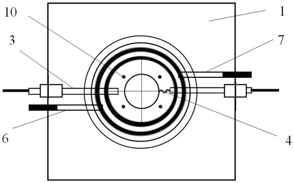
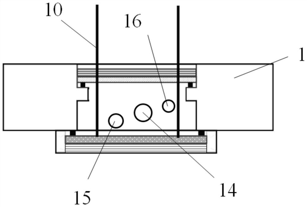
[0075] A visualized biofilm culture reactor, such as Figure 1 ~ Figure 4 As shown, the reactor body, reference electrode 3 and counter electrode 4 are included, the reactor body has a reaction chamber, and the side wall of the reactor body has a water inlet 15 and a water outlet 16 communicating with the reaction chamber and the outside, The water inlet 15 is installed with the water inlet pipe joint 6, and the water outlet 16 is equipped with the water outlet pipe joint 7, and the joints are all sealed. The side wall of the reactor main body is also provided with an electrode slot 14, and the reference electrode 3 and the counter electrode 4 pass through the reaction. The electrode socket 14 on the side wall of the device main body extends into the reaction chamber.

[0076] The main body of the reactor includes a body 1, a light-transmitting bottom plate 2, a cover 5, an upper fastening ring 8, a lower fastening ring 9, a conductive probe 10, a sealing gasket 11 and a clamp...

Embodiment 2

[0094] The transparent bottom plate is made of transparent glass whose inner surface is a conductive surface, and the conductive surface is used as a working electrode, which is connected to the electrochemical workstation through a conductive probe. Such as Figure 5 and Figure 6 As shown, one conductive probe 10 is provided, which passes through the body 1 and is detachably connected to the inner surface of the transparent bottom plate. The structure of the conductive probe is as Figure 8 As shown, the solid pipe section is fixedly connected to the body 1 instead of the cover, and runs through the body from the second step formed by the through hole and the hollow cavity.

[0095] Except for the light-transmitting bottom plate and the conductive probes, other settings are the same as those in Embodiment 1, and will not be repeated here.

[0096] A kind of application example corresponding to this embodiment 2:

[0097] The specific size settings are as follows:

[009...


PUM

PropertyMeasurementUnit
thicknessaaaaaaaaaa
diameteraaaaaaaaaa

Abstract

The invention discloses a visual biological membrane culture reactor and an in-situ observation method; the reactor comprises a reactor main body, a reference electrode and a counter electrode; the reference electrode and the counter electrode penetrate through the side wall of the reactor main body and extend into a reaction chamber; the reactor main body comprises a body, a sealing cover, a clamping part, a light-transmitting bottom plate and a conductive probe; the body is provided with a through hollow cavity; the sealing cover is sealed and detachably connected with a port at one end of the hollow cavity; a transparent skylight is arranged in the centre of the sealing cover; the clamping part protrudes outwards relative to the bottom surface of the body; a through hole coaxially penetrating through the hollow cavity is formed in the clamping part; the light-transmitting bottom plate is sealed and detachably connected with a port at the other end of the hollow cavity or the through hole of the clamping part; the inner surface of the light-transmitting bottom plate is a conductive surface or a conductive glass sheet is arranged on the inner side of the light-transmitting bottom plate; one end of the conductive probe extends into the reaction chamber and is in clutch connection with the conductive surface or the conductive glass sheet; and the other end of the conductive probe extends out of the body. According to the invention, the bottlenecks of in-situ sampling, in-situ dyeing and in-situ confocal observation and detection are overcome.

Description

technical field [0001] The invention relates to the technical field of microbial electrochemistry, in particular to a visualized biofilm cultivation reactor and a method for cultivating and observing biofilm using the reactor. Background technique [0002] At present, biofilm has become a research hotspot in the fields of medicine, food and environment. However, until now, biofilm is still a "black box", and the material circulation, community structure and function in the membrane have yet to be explored. In 2004, Logan et al. (Liu H, Ramnarayanan R, Logan BE. Production of electricity during wastewater treatment using a single chamber microbial fuel cell [J]. Environ Sci Technol, 2004, 38 (7): 2281-2285) found that from wastewater The electron transfer efficiency of the enriched biofilm adsorbed on the solid electrode is hundreds of times that of planktonic microorganisms. This type of biofilm formed by microorganisms that can exchange electrons with conductive materials...

Claims


Application Information

Patent Timeline
Patent Type & Authority Applications(China)
IPC IPC(8): C12M1/34C12M1/00G01N21/84C02F3/00
CPCC12M23/22C12M23/48C12M23/38C12M23/46C12M41/46G01N21/8422C02F3/005
Inventor 冯华军郭薇丁养城徐颖峰洪智程金阿南肖咪
Owner ZHEJIANG GONGSHANG UNIVERSITY
Why Eureka
Try Eureka