Equipment for extracting precious metal in automobile exhaust catalyst
A technology for extraction equipment and automobile exhaust, applied in the direction of improving process efficiency, etc., can solve problems such as reduced service life, thermal fatigue effect of peripheral components, and overflow of catalytic temperature of extraction device, so as to reduce size, ensure thoroughness, and degree of freedom high effect
- Summary
- Abstract
- Description
- Claims
- Application Information
AI Technical Summary
Problems solved by technology
Method used
Image
Examples
Embodiment 1
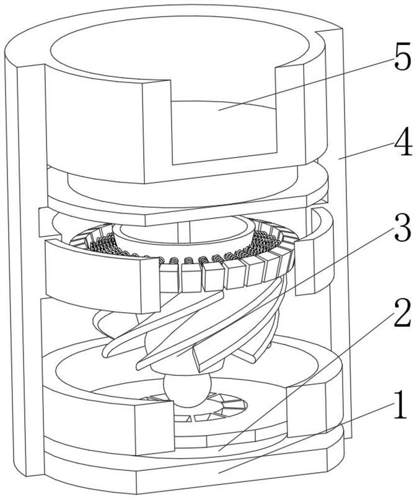
[0039] see Figure 1-2 , the present invention provides a technical solution: a kind of precious metal extraction equipment in automobile exhaust catalyst, specifically comprising:
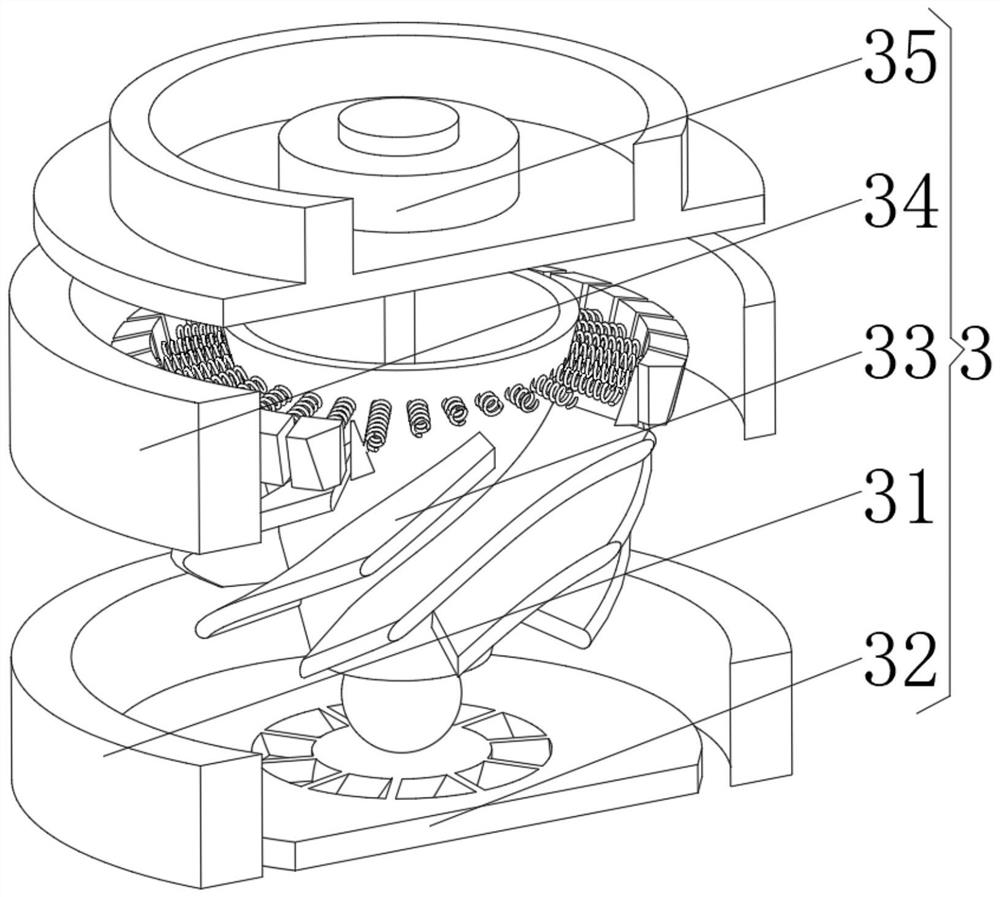
[0040]Seat plate 1, the seat plate 1 has a circular plate body, and the centrifugal extraction device 3 installed on the top of the circular plate body is fixedly connected with the air fan 2 and installed on the top of the air fan 2, and is installed on the outer surface of the circular plate body The protective arc plate 4, and the bearing cylinder 5 installed on the top of the centrifugal extraction device 3, through the design of the air fan 2, the overall component is driven by wind force, and the spiral generated by the wind force forms a wind-forced airflow barrier, which protects the centrifugal extraction device in the equipment. 3. Carry out temperature isolation to maintain the temperature of the centrifugal extraction device 3 and ensure the thoroughness of the extraction by the centri...
Embodiment 2
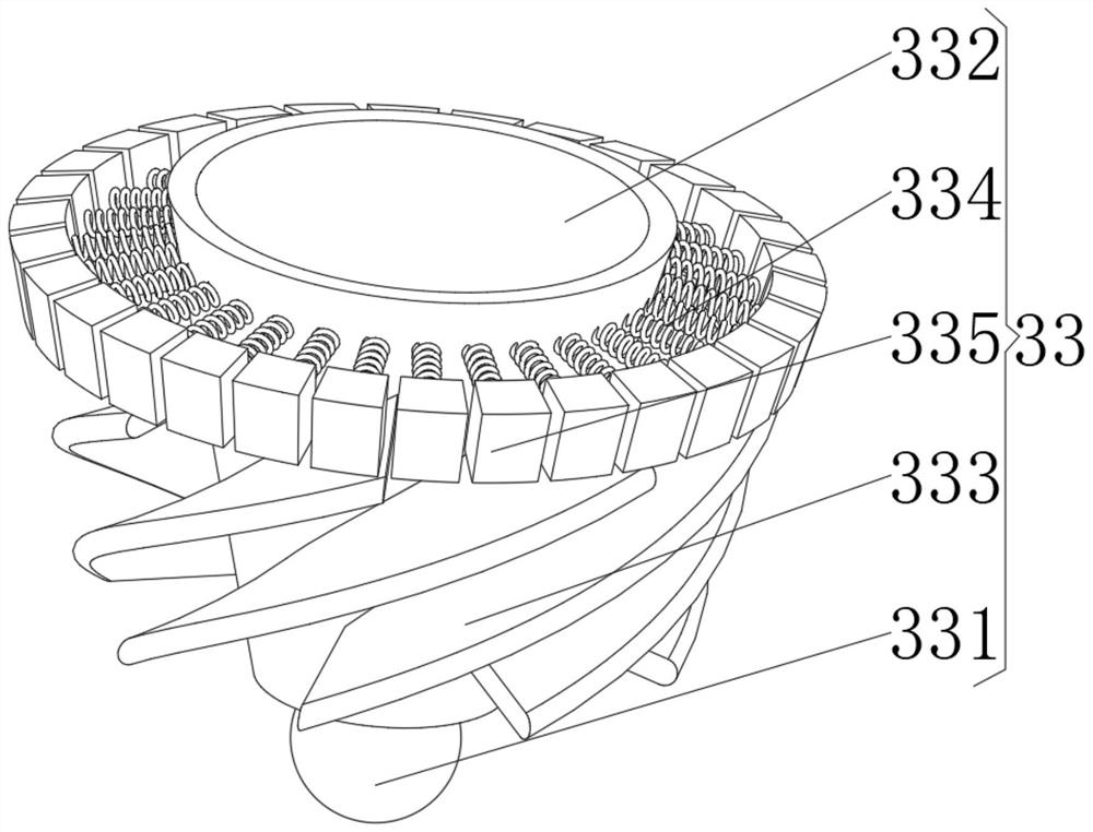
[0045] see Figure 1-4 On the basis of Embodiment 1, the present invention provides a technical solution: the extraction device 33 includes:
[0046] Mounting part 331, the mounting part 331 has a spherical main body, and an extraction cylinder 332 installed on the top of the spherical main body, and a wind blade 333 installed in the middle of the outer surface of the extraction cylinder 332, and installed on the top of the extraction cylinder 332 outer surface The protection spring 334 is installed on the protection block 335 at the end of the protection spring 334 away from the extraction cylinder 332 . Through the spherical main body design of the mounting part 331, the contact area between the extraction device 33 and the bottom air fan 2 is reduced, the friction force is reduced, and the rotation of the extraction device 33 is facilitated. At the same time, the extraction device 33 has a high degree of freedom as a whole. It is convenient for adjustment in all directions...
Embodiment 3
[0053] see Figure 1-5 , On the basis of Embodiment 1 and Embodiment 2, the present invention provides a technical solution: the liquid injection device 35 includes:
[0054] Positioning plate 351, the positioning plate 351 has a circular plate body, and the injection pump 352 installed on the top of the circular plate body, and the spacer ring plate 353 installed on the circular plate body outside the injection pump 352, and installed on the circular plate body The liquid injection pipe 354 at the middle position of the bottom of the plate body, the ball joint 355 installed at the bottom of the liquid injection pipe 354 , and the trifurcated branch rod 356 installed at the bottom of the ball joint 355 . Through the design of the three-pronged rod 356, the pressure of the liquid can be used for dispersed injection during the liquid injection, and the injection at an angle can make the extraction liquids mix with each other during injection, making the extraction more uniform a...
PUM
 Abstract
Description
Claims
Application Information
 - R&D
- Intellectual Property
- Life Sciences
- Materials
- Tech Scout
- Unparalleled Data Quality
- Higher Quality Content
- 60% Fewer Hallucinations
Browse by: Latest US Patents, China's latest patents, Technical Efficacy Thesaurus, Application Domain, Technology Topic, Popular Technical Reports.
© 2025 PatSnap. All rights reserved.Legal|Privacy policy|Modern Slavery Act Transparency Statement|Sitemap|About US| Contact US: help@patsnap.com


