Stripping method and equipment for hydrocarbon catalytic converting catalyst

A catalytic conversion and catalyst technology, which is applied in the field of petrochemical industry, can solve the problems of difficult manufacturing and installation, complex packing structure of the stripper, etc., and achieve the effects of reducing back-mixing, improving gas-solid contact efficiency, reducing short-circuit and back-mixing

Inactive Publication Date: 2004-01-28
SINOPEC LUOYANG PETROCHEM ENG CORP +1
View PDF3 Cites 5 Cited by
  • Summary
  • Abstract
  • Description
  • Claims
  • Application Information

AI Technical Summary

Problems solved by technology

But the packing structure of the stripper disclosed by the above two patent documents is complicated, and it is difficult to manufacture and install

Method used


Image

  • Stripping method and equipment for hydrocarbon catalytic converting catalyst
  • Stripping method and equipment for hydrocarbon catalytic converting catalyst
  • Stripping method and equipment for hydrocarbon catalytic converting catalyst

Examples


Embodiment Construction

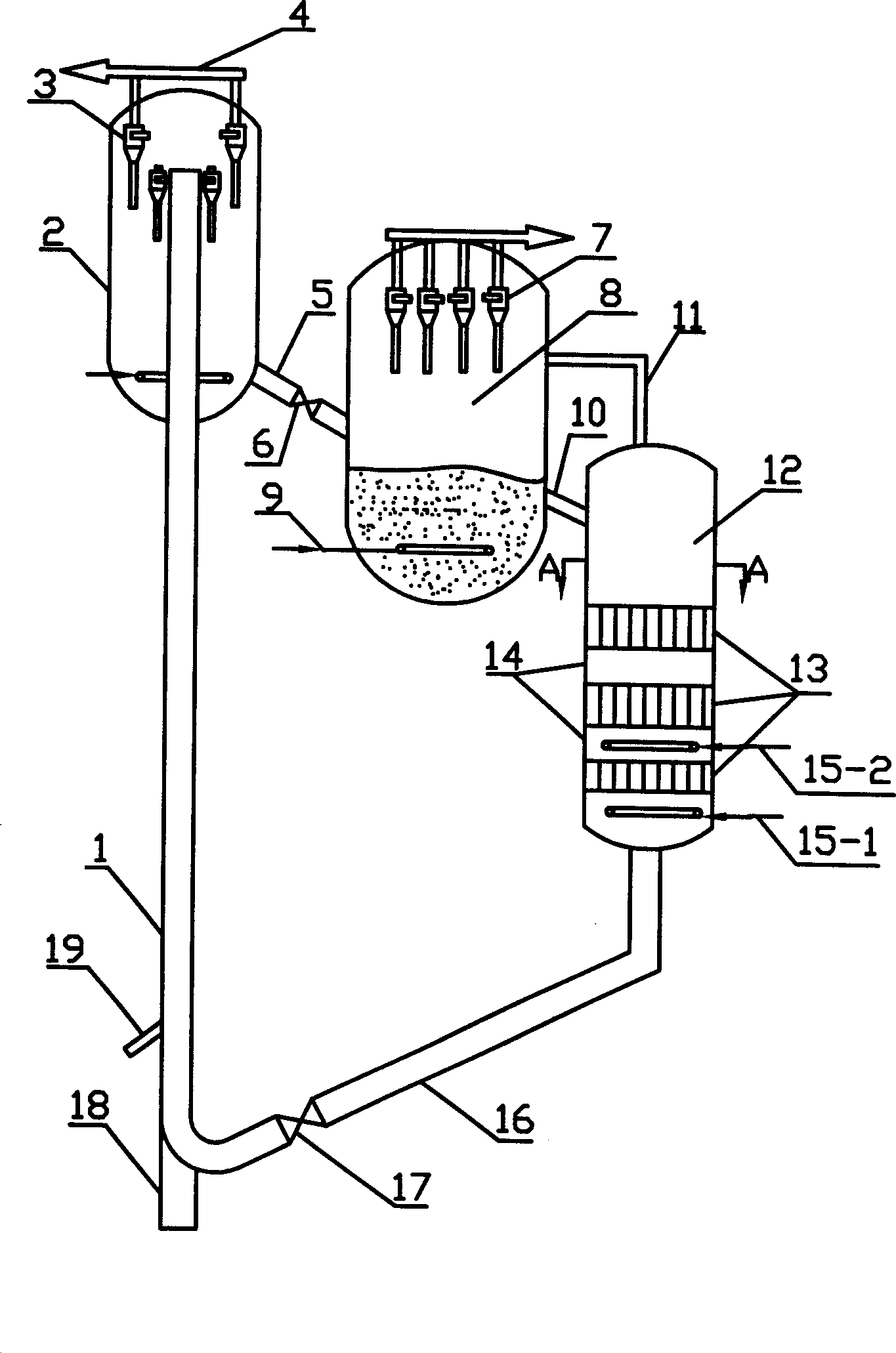
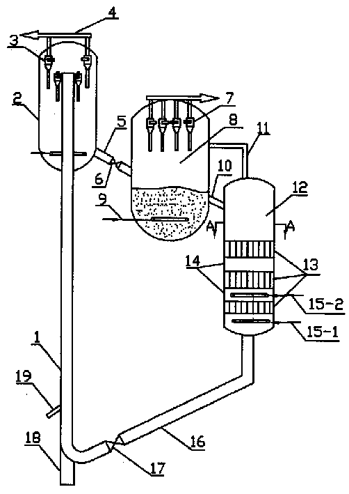
[0017] Such as figure 1 As shown, the hydrocarbon feedstock coming in from the bottom line 19 contacts the catalyst particles coming in from the catalyst outlet pipe 16 in the riser 1 , and the pre-lift steam enters the riser 1 from the gas line 18 .

[0018] The top of the riser 1 is connected to the settler 2 . The separation of the conversion products and the stripping of the deactivated catalyst take place in the settler 2 . The treated raw material is separated in the cyclone 3 located at the top of the settler 2, and the converted stream after the separation goes out of the settler 2 from the outlet line 4, and at the same time, the deactivated catalyst flows downward by gravity into the bottom of the settler 2, A general deactivated catalyst stripping is performed. The deactivated catalyst after stripping flows out from the bottom of the settler 2 and passes through the delivery pipeline 5 to the regenerator 8, on which a control valve 6 is installed. In the regenera...


PUM


Abstract

The present invention provides one method of raising the efficiency of stripping hydrocarbon converting catalyst and its equipment. According to the present invention, catalyst particle and stripping fluid are made to counterflow through one stripper with at least two layers of stuffing. The stuffing in the stuffing layers is crossed into diamond shaped grid plate parallel to the axis of the stripper. The stripper of the present invention has high efficiency. The present invention is especially suitable for catalytic conversion process of preparing olefin, the smoke impurity content in the regenerating agent is less than 0.05 vol%, and the stripper can be reduced in volume and equipment investment obviously.

Description

technical field [0001] The invention belongs to the field of petrochemical industry, and relates to a catalytic conversion method and equipment for hydrocarbon raw materials, in particular to a stripping method and equipment for improving the stripping efficiency of catalytic conversion catalysts. Background technique [0002] The traditional fluid catalytic cracking technology (FCC) is mainly used to produce gasoline, diesel and a small amount of liquefied gas. During the reaction process, coke deposits on the catalyst particles need to be burnt to regenerate. After the raw catalyst is burnt and regenerated in the regenerator, it can be reused. [0003] With the pursuit of economic benefits and the increasingly heavy processing of crude oil, the FCC unit is required to have better flexibility and adaptability. Therefore, not only useful FCC plant produces gasoline recently, but also adopts the trend of FCC plant to produce petrochemical raw materials such as ethylene, prop...

Claims


Application Information

Patent Timeline
Patent Type & Authority Patents(China)
IPC IPC(8): C10G35/04
Inventor 张振千匡卓贤张立新郭奇刘昱胡杰毕志予李宏冰田耕
Owner SINOPEC LUOYANG PETROCHEM ENG CORP
Why Eureka
Try Eureka